

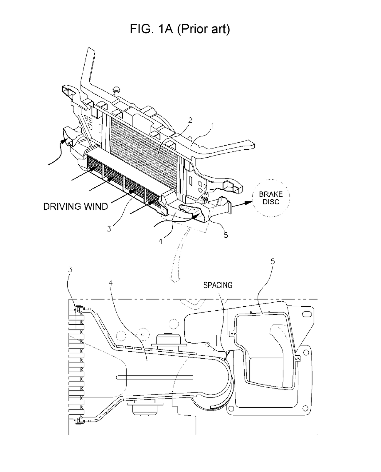
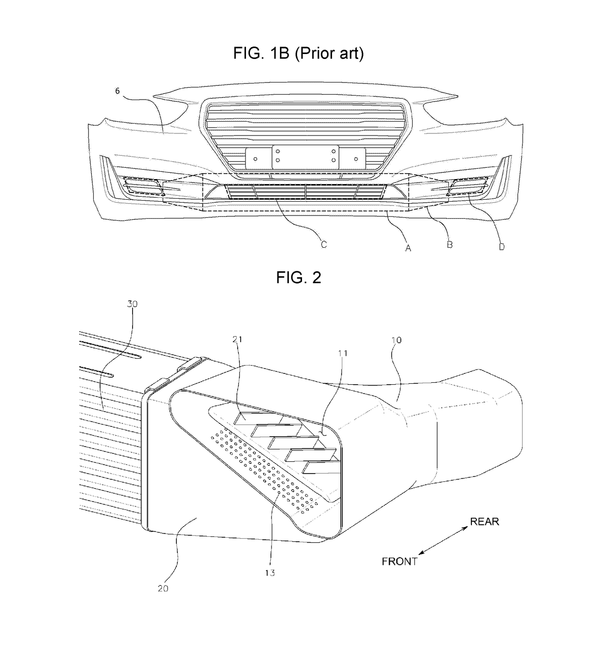
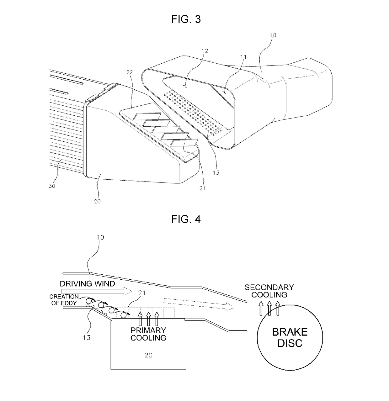
Structure of brake-cooling duct
a technology of brake cooling duct and structure, which is applied in the direction of braking system, machine/engine, sub-unit features of vehicles, etc., can solve the problems of reducing the cooling efficiency of the intercooler and the brake cooling duct, and complicating the attachment of the same to the vehicle body, so as to maximize the brake cooling duct, and facilitate assembly. , the effect of maximizing the cooling efficiency of the intercooler
- Summary
- Abstract
- Description
- Claims
- Application Information
AI Technical Summary
Benefits of technology
Problems solved by technology
Method used
Image

Examples
Embodiment Construction
[0030]Reference will now be made in detail to various embodiments of the present invention(s), examples of which are illustrated in the accompanying drawings and described below. While the invention(s) will be described in conjunction with exemplary embodiments, it will be understood that the present description is not intended to limit the invention(s) to those exemplary embodiments. On the contrary, the invention(s) is / are intended to cover not only the exemplary embodiments, but also various alternatives, modifications, equivalents and other embodiments, which may be included within the spirit and scope of the invention as defined by the appended claims.
[0031]Reference will now be made in detail to the embodiments of the present invention, examples of which are illustrated in the accompanying drawings, to allow those skilled in the art to easily understand and reproduce the embodiments of the present invention. However, the present invention may be implemented in various differen...
PUM
 Abstract
Description
Claims
Application Information