Cooling circuit of oil cooler for vehicle

a technology of oil cooler and cooling circuit, which is applied in the direction of mechanical equipment, machines/engines, lubricant mounting/connection, etc., can solve the problems of limited oil cooler series structure, insufficient oil cooling only by heat radiation in the oil pan, and relatively decreased cooling efficiency, so as to achieve the effect of maximizing cooling efficiency and providing higher flux

Inactive Publication Date: 2008-05-15
HYUNDAI MOTOR CO LTD
View PDF9 Cites 5 Cited by
  • Summary
  • Abstract
  • Description
  • Claims
  • Application Information

AI Technical Summary

Benefits of technology

[0008]Embodiments of the present invention provide a cooling circuit of an oil cooler for a vehicle includes an independent and shorter circuit that receives a cooling water of the lowest temperature through an entrance of a cylinder block to cool the oil cooler and directly connects the cooling water of the oil cooler to a water pump intake and, thus, it can supply higher flux to small flow paths due to the large difference of the pressure and maximize the cooling efficiency due to the large difference of the temperature, since it cools only the oil cooler with the introduced cooling water and the cooling circuit of the oil cooler is directly connected to a water pump intake of the lowest pressure.

Problems solved by technology

Oil heated in the process of cooling the respective regions of the engine radiates the heat while it is returned to an oil pan; however, the oil cooling only by the radiation of heat in the oil pan is insufficient in an engine running at high speed, thus using a separate oil cooler.
However, there have been various complicated problems in that the size of the oil cooler in the series structure is restrictive and the oil cooler in the parallel structure should use pipes, while it has an advantage in term of a layout.
For example, if a lot of resistance is given to the cooling water flow in the conventional oil cooler, the cooling efficiency is relatively decreased and its capability of regulating temperature is lowered and, further, since the size of the oil cooler is large, it occupies a large volume in the engine layout.

Method used


Image

  • Cooling circuit of oil cooler for vehicle
  • Cooling circuit of oil cooler for vehicle
  • Cooling circuit of oil cooler for vehicle

Examples


Embodiment Construction

[0020]Hereinafter, exemplary embodiments of the present invention will now be described in detail with reference to the attached drawings.

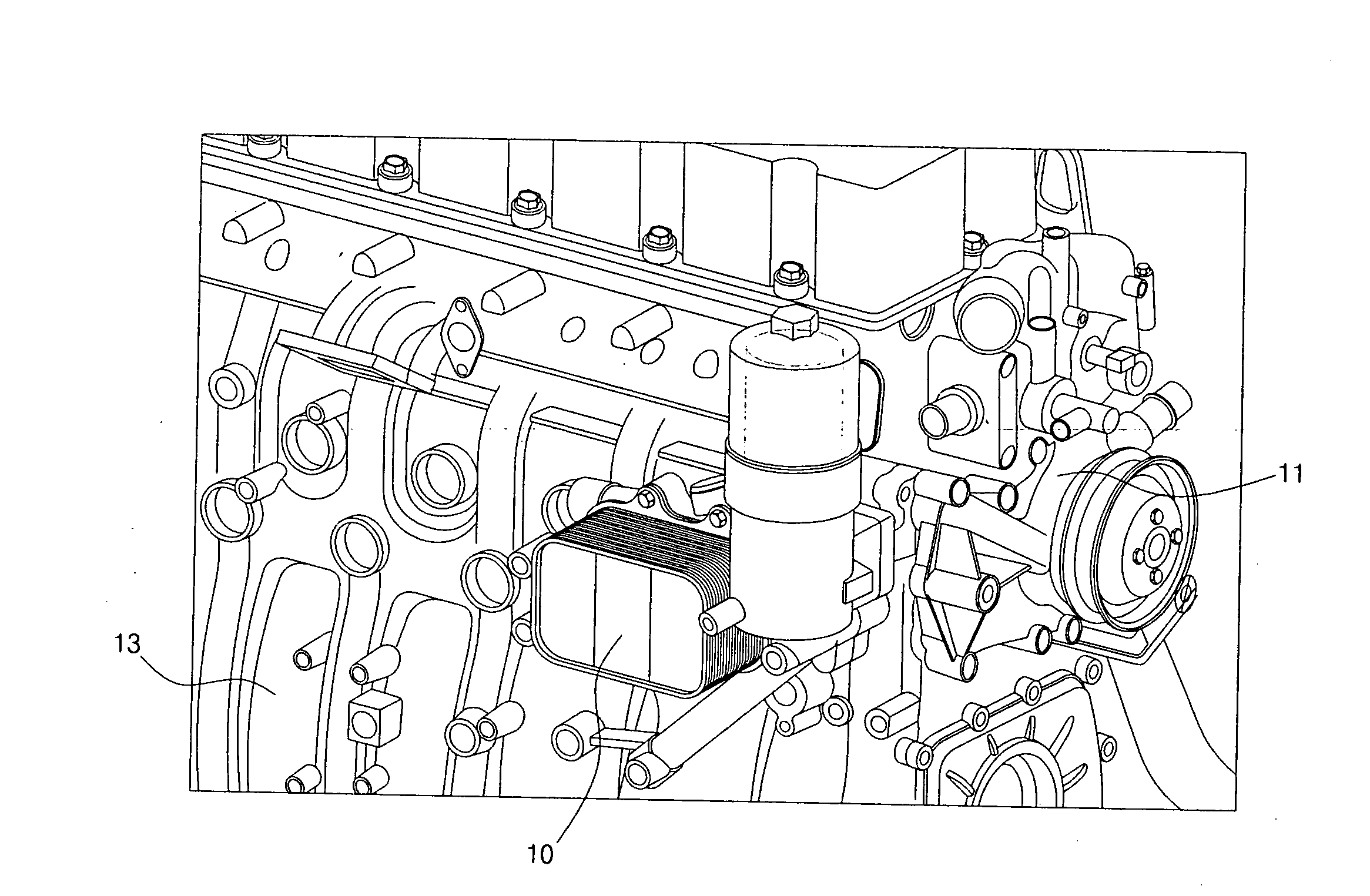
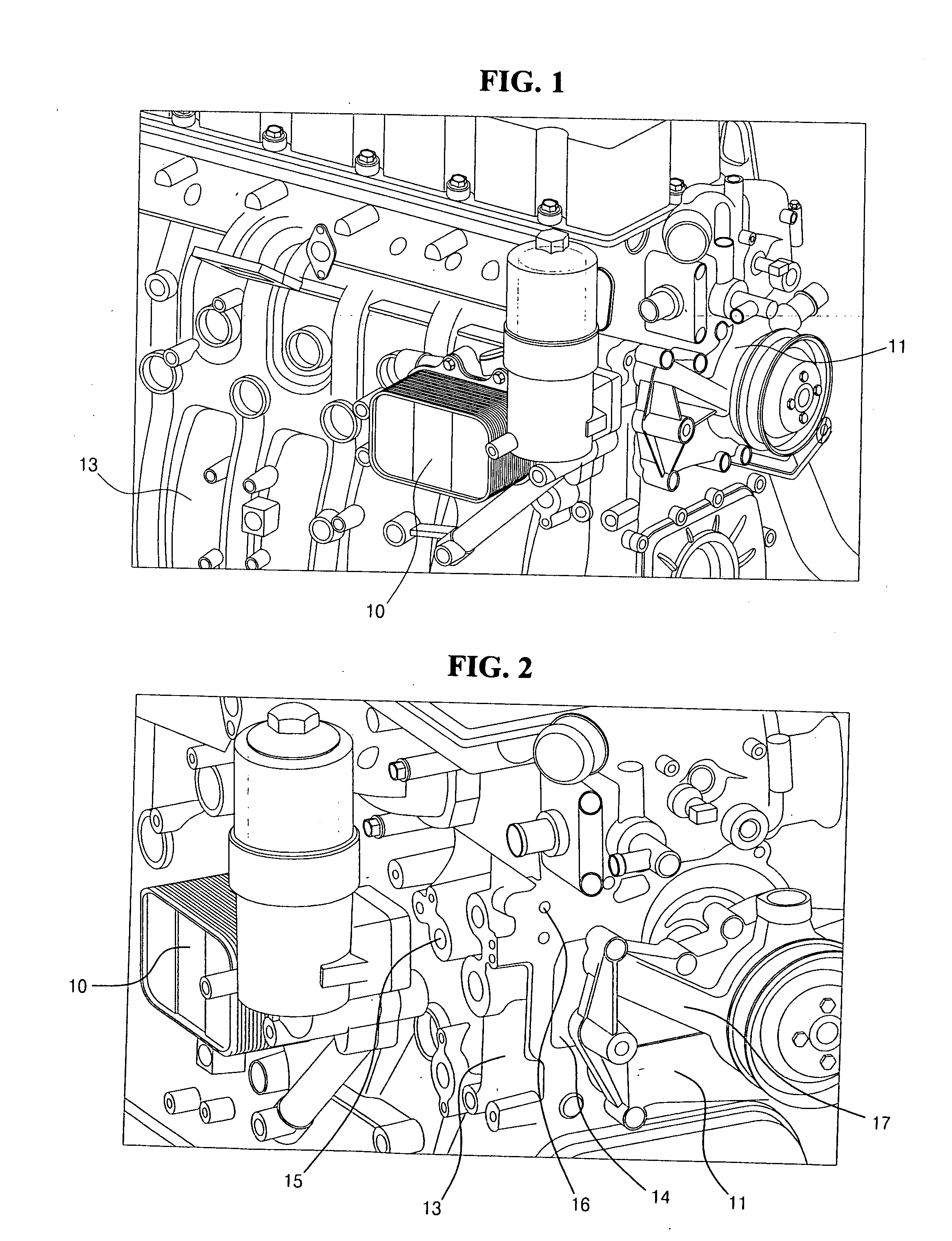
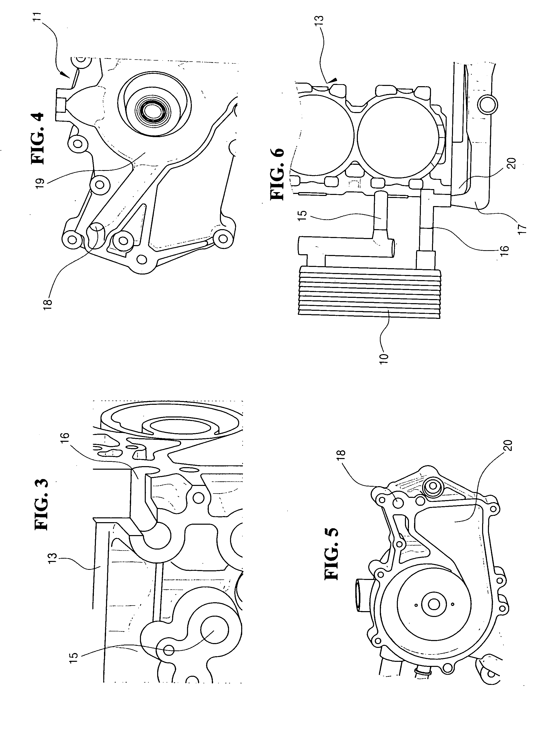
[0021]Referring to FIGS. 1-3, a cooling circuit of an oil cooler 10 comprises a cooling water inlet 14 formed in a cylinder block 13, through which a cooling water flowing in a radiator 12 is introduced via a water pump 11, and an oil cooler inlet 15 established to supply the cooling water introduced into the cylinder block 13 to the oil cooler 10.

[0022]Moreover, the cooling circuit of the oil cooler 10 further comprises an oil cooler outlet 16, arranged in parallel to the oil cooler inlet 15, through which the cooling water supplied to the oil cooler 10 to cool the oil cooler 10 only is provided to the cylinder block 13.

[0023]For the configuration of the cooling circuit of the oil cooler 10, a path 17 for collecting cooling water is established, though which the cooling water heated via the heat exchange with the oil cooler 10 is collected to the...


PUM


Abstract

A cooling circuit of an oil cooler for a vehicle that reduces the number of parts and provides an elegance appearance of the engine by applying a cooling circuit structure of a parallel type oil cooler having a good layout and a high cooling efficiency to configure the cooling circuit of the oil cooler having a simplified and independent flow path structure without any pipe coming out of the engine. The cooling circuit receives a cooling water of the lowest temperature through a cooling water inlet formed in a cylinder block to cool the oil cooler and directly connects the cooling water of the oil cooler to a cooling water intake established in a water pump.

Description

CROSS-REFERENCE TO RELATED APPLICATION[0001]This application claims the benefit of Korean Patent Application No. 10-2006-0111556, filed on Nov. 13, 2006, the entire disclosure of which is hereby incorporated by reference.BACKGROUND OF THE INVENTION[0002]1. Field of the Invention[0003]The present invention relates to a cooling circuit of an oil cooler for a vehicle and, more particularly, to a cooling circuit having a simplified and independent flow path structure without any pipe coming out of the engine.[0004]2. Description of Related Art[0005]In general, a vehicle engine is composed of various parts such as cylinder block, cylinder head, piston, crank shaft, connecting rod, cam, etc. While such parts operate at high speed, heat is always produced in the regions where the parts are into contact with each other and, accordingly, the respective friction regions and sliding regions are to be cooled and lubricated using lubricants (oil). That is, the oil functions to remove the heat pr...

Claims


Application Information

Patent Timeline
Patent Type & Authority Applications(United States)
IPC IPC(8): F01M11/03
CPCF01P11/04F01P2003/028F01P11/08F01P3/12F01M5/00
Inventor LEE, KANG HYEOK
Owner HYUNDAI MOTOR CO LTD
Why Eureka
Try Eureka