
State prediction system

a technology of state prediction and object, applied in the field of object state prediction, can solve problems such as unstable prediction precision, and achieve the effect of improving the stability of candidate trajectory specification

Active Publication Date: 2019-01-01
HONDA MOTOR CO LTD
View PDF8 Cites 0 Cited by
  • Summary
  • Abstract
  • Description
  • Claims
  • Application Information

AI Technical Summary

Benefits of technology

[0006]Accordingly, an object of the present invention is to provide a system that can enhance stability of a result of predicting the state of an object.

Problems solved by technology

However, depending on conditions of predicting the state of an object, predicted states may become unstable as they vary with high frequency, or prediction precision may become unstable.

Method used


Image

  • State prediction system
  • State prediction system
  • State prediction system

Examples


example

[0055]A description is give of the case illustrated in FIG. 4. In FIG. 4, a humanoid robot 21 and a human 22 face each other across a table 20. In this state, the state prediction system 1 mounted on the robot 21 predicts the state of a right hand of the human 22 as an object. The robot 21 is configured as described in Japanese Patent No. 5489965 for example, and a detailed description thereof is omitted.

[0056]Laid on the table 20 are two cups 31 and 32 and one tray 34. Representative positions of eight regions are each defined as candidate positions (candidate states) x1 to x8. The regions include: (1) a right-side cup 31 and (2) a left-side cup 32 as viewed from the robot 21, four blocks of the tray 34 including (3) a front right-side block, (4) a front left-side block. (5) a rear right-side block, and (6) a rear left-side block, and edges of the tray 34 including (7) a right-side edge and (8) a left-side edge. The state estimation element 10 time-serially estimates a position x0 ...


PUM


Abstract

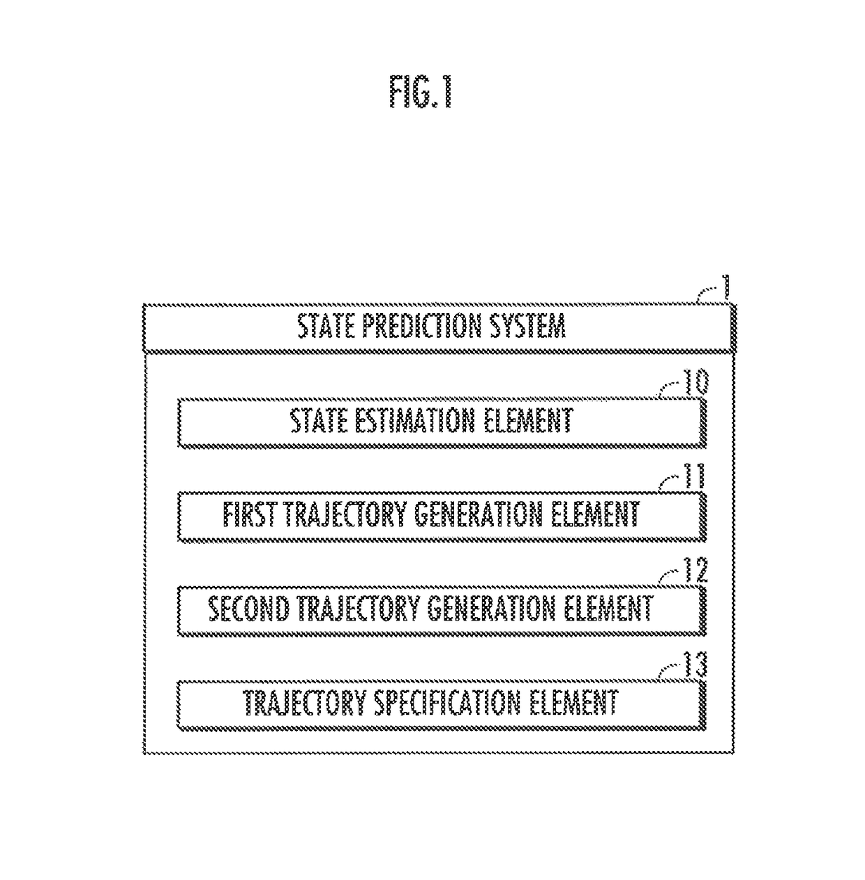
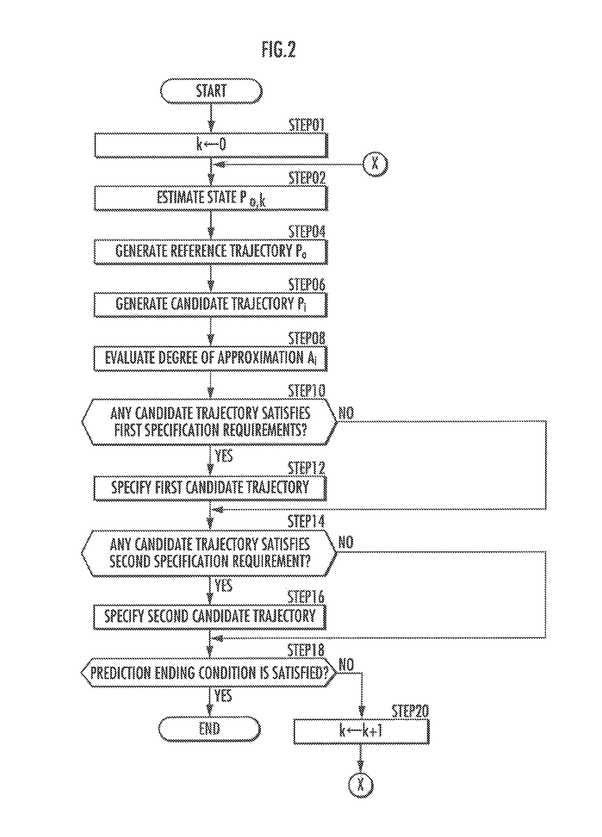
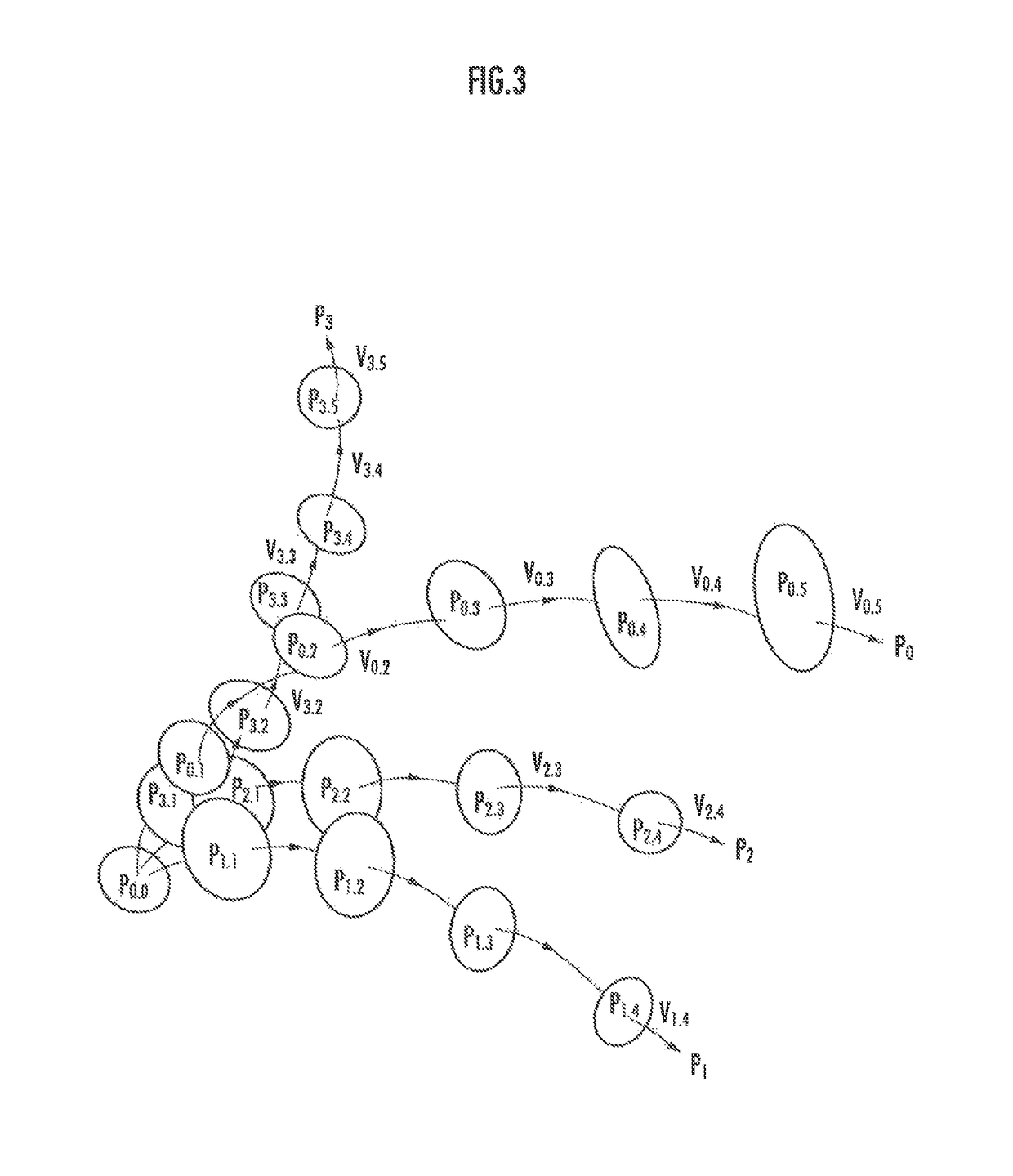
To provide a system that can enhance stability of a result of predicting the state of an object. At least one candidate trajectory having a degree of approximation to a reference trajectory generated based on a current state of the object being in a specified rank or higher over a first specification period is specified as “a first candidate trajectory”. At least one candidate trajectory, extending from a last time point of being the first candidate trajectory to before elapse of a second specification period, is specified as “a second candidate trajectory”. Accordingly, it becomes possible to enhance stability of the specification result of the candidate trajectory as a result of predicting the state of the object.

Description

BACKGROUND OF THE INVENTION[0001]1. Field of the Invention[0002]The present invention relates to a technique for predicting the state of an object.[0003]2. Description of the Related Art[0004]When robots operate in the same environment as humans, motions of the robots need adaptive change corresponding to the movement of objects including the humans. Accordingly, methods for predicting the state of an object have been proposed (see Japanese Patent Laid-Open No. 2013-143134, Japanese Patent Laid-Open No. 2013-196601, Japanese Patent Laid-Open No. 2013-054703, and Japanese Patent No. 5489965).[0005]However, depending on conditions of predicting the state of an object, predicted states may become unstable as they vary with high frequency, or prediction precision may become unstable.SUMMARY OF THE INVENTION[0006]Accordingly, an object of the present invention is to provide a system that can enhance stability of a result of predicting the state of an object.[0007]The state prediction sys...

Claims


Application Information

Patent Timeline
Patent Type & Authority Patents(United States)
IPC IPC(8): G06F7/60G06F17/10B25J9/16G06F17/50
CPCB25J9/1664Y10S901/02G06F17/50G05B2219/40521G06F30/00
Inventor IBA, SOSHI
Owner HONDA MOTOR CO LTD
Learn More