Vehicle shift control system

a technology of shift control and shift indicator, which is applied in the direction of braking system, dynamo-electric gear control, electric devices, etc., can solve the problems of reducing the charging efficiency of plug-in charging, indicating not particularly useful information to users, and preventing the illumination of lock indicator lamps from dazzling users

Active Publication Date: 2019-01-01
TOYOTA JIDOSHA KK
View PDF28 Cites 0 Cited by
  • Summary
  • Abstract
  • Description
  • Claims
  • Application Information

AI Technical Summary

Benefits of technology

[0010]By so doing, when the locked state is set on the basis of a predetermined request signal for setting the locked state, the lock indicator lamp is turned on or off on the basis of the status of power supplied to the vehicle. Therefore, for example, when the status of power supplied to the vehicle is a power off status, or the like, where the display device for indicating vehicle information related to vehicle driving is not turned on, the lock indicator lamp may be reliably turned off. This prevents indication of not particularly useful information, such as illumination of the lock indicator lamp at the time of parking lock without shift operation, to a user. Therefore, this prevents the illumination from dazzling the user in the power off status, or the like. In addition, for example, when the status of power supplied to the vehicle is a power on status, or the like, for turning on the display device for indicating vehicle information related to vehicle driving to enable the vehicle to run, the lock indicator lamp may be reliably turned on. By so doing, for example, even when not particularly useful information, such as illumination of the lock indicator lamp at the time of parking lock without shift operation, is indicated to the user, the display device for indicating the vehicle information may possibly remain turned on, so this prevents the illumination of the lock indicator lamp from dazzling the user. In addition, for example, the lock indicator lamp may also be turned off in the power off status, or the like, during plug-in charging, so this prevents a possible decrease in the charging efficiency of plug-in charging due to the illumination of the lock indicator lamp. Other than the above, the lock indicator lamp is uniformly turned on or off on the basis of the status of power supplied to the vehicle, so it is possible to uniformly indicate a vehicle state for user's same operation, and this prevents a possible misunderstanding of the user as a malfunction, or the like. In this way, when the locked state is set on the basis of the predetermined request signal for setting the locked state, it is possible to appropriately turn on or off the lock indicator lamp.
[0011]Here, when the status of power supplied to the vehicle is a power off status for disabling the vehicle from running, or when the status of power supplied to the vehicle is raised from the power off status to a partially power on status for disabling the vehicle from running but allowing operation of only part of functions of the vehicle while a display device for indicating vehicle information related to vehicle driving remains turned off, the lock indicator lamp may be turned off. For example, this prevents indication of not particularly useful information, such as illumination of the lock indicator lamp at the time of parking lock without shift operation, to the user, and also prevents the illumination from dazzling the user when the status of power is the power off status or when the status of power is raised to the partially power on status. In addition, for example, it is possible to turn off the lock indicator lamp when the status of power is the power off status or is raised to the partially power on status during plug-in charging, so this prevents a possible decrease in the charging efficiency of plug-in charging due to the illumination of the lock indicator lamp. Other than the above, the lock indicator lamp is uniformly turned off when the status of power is the power off status or is raised to the partially power on status, so this prevents a possible misunderstanding of the user as a malfunction, or the like.
[0013]In addition, the lock indicator lamp may be turned on within a predetermined period of time from when the charging is started. This prevents the illumination of the lock indicator lamp from dazzling the user at the time of charging the electrical storage device. In addition, this prevents a decrease in the charging efficiency at the time of charging the electrical storage device. Other than the above, this prevents a possible misunderstanding of the user as a malfunction, or the like, at the time of charging the electrical storage device.
[0014]In addition, when the status of power supplied to the vehicle is a power on status for turning on a display device for indicating vehicle information related to vehicle driving to enable the vehicle to run, the lock indicator lamp may be turned on. By so doing, for example, the display device for indicating vehicle information may be turned on in the power on status, so this prevents the illumination of the lock indicator lamp from dazzling the user. Other than the above, the lock indicator lamp is uniformly turned on in the power on status, so this prevents a possible misunderstanding of the user as a malfunction, or the like.

Problems solved by technology

Such illumination of the lock indicator lamp based on parking lock without shift operation indicates not particularly useful information to a user.
In a power off status, or the like, where a display device for indicating vehicle information related to vehicle driving is not turned on, the illumination may possibly dazzle the user.
In addition, particularly, when the external factor is plug-in charging, there is a possibility that the charging efficiency of plug-in charging decreases because of illumination of the lock indicator lamp.
By so doing, indication of a parking lock state differs even with the same operation, so a user may misunderstand it as a malfunction, or the like.
This prevents indication of not particularly useful information, such as illumination of the lock indicator lamp at the time of parking lock without shift operation, to a user.
In addition, for example, the lock indicator lamp may also be turned off in the power off status, or the like, during plug-in charging, so this prevents a possible decrease in the charging efficiency of plug-in charging due to the illumination of the lock indicator lamp.

Method used


Image

  • Vehicle shift control system
  • Vehicle shift control system
  • Vehicle shift control system

Examples


Embodiment Construction

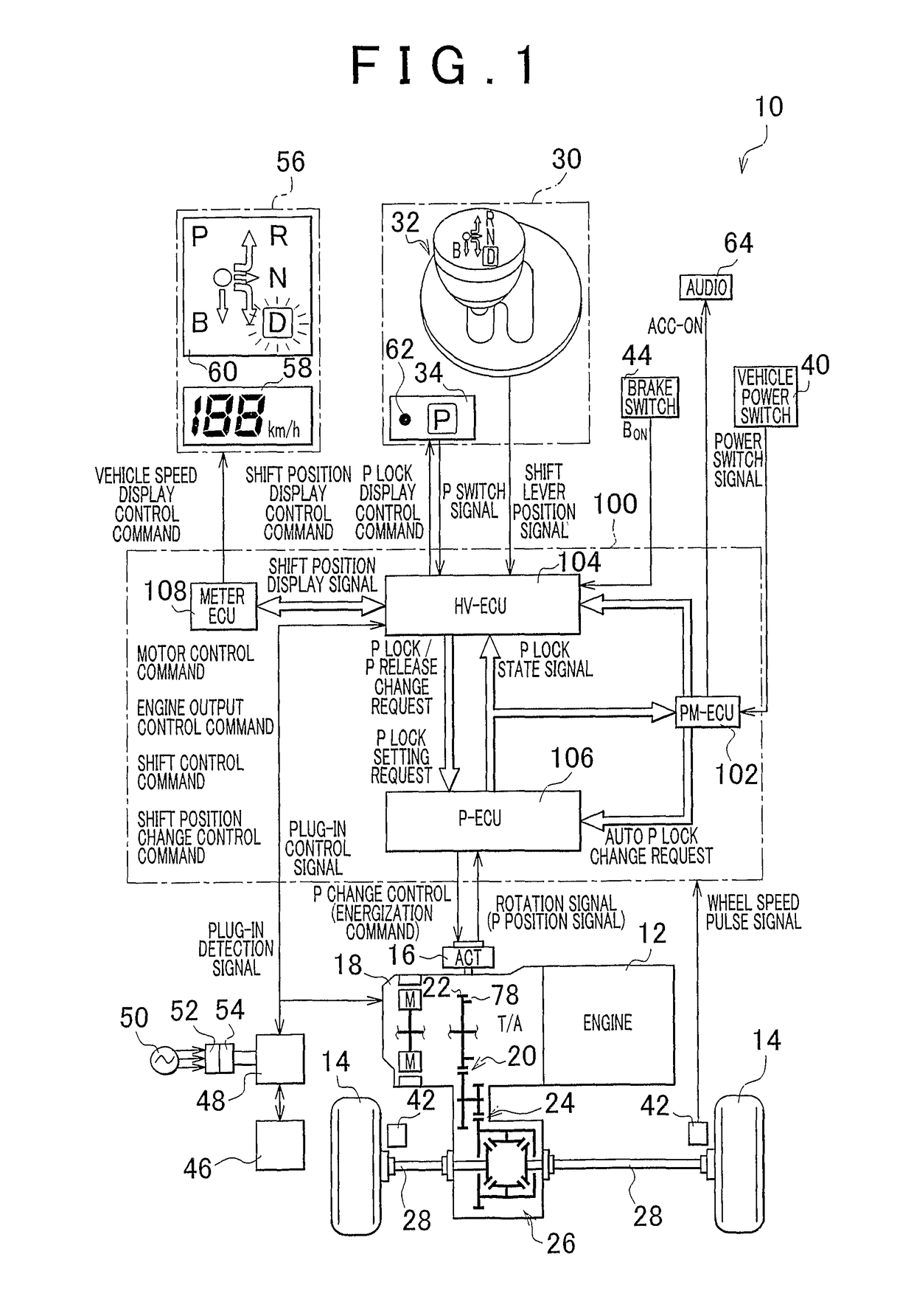
[0031]FIG. 1 is a view that illustrates the schematic configuration of a power transmission path from an engine 12 to drive wheels 14. The power transmission path constitutes a vehicle 10 to which an embodiment of the invention is applied. FIG. 1 is also a block diagram that illustrates a relevant portion of a control system provided for the vehicle 10 in order to control a parking lock device 16, and the like. As shown in FIG. 1, the vehicle 10 includes the parking lock device 16, a transmission 18, a shift operating device 30, and the like, and employs a shift-by-wire (SBW) system that electrically changes a shift position, that is, a shift position (shift range) of the transmission 18, for vehicle driving. In addition, the transmission 18 is, for example, suitably used for a front-engine rear-drive (FF) vehicle in which the transmission 18 is transversely arranged in the vehicle 10. Power of the engine 12 is transmitted from an output gear 22 to the pair of drive wheels 14 via a ...


PUM


Abstract

When a P lock state is set on the basis of a predetermined request signal for setting the P lock state, a P position indicator lamp (62) is turned on or off on the basis of the status of power supplied to the vehicle (10). For example, when the P lock state is set, the P position indicator lamp (62) is turned off when the power status is an ALL-OFF status where a combination meter (56), or the like, is not turned on or is raised to an ACC-ON status; whereas, when the P lock state is set, the P position indicator lamp (62) is turned on when the power status is an IG-ON status, when the power status is changed from the IG-ON status during vehicle driving to the ACC-ON status, or within a predetermined period of time from when the power status is changed from the IG-ON status to the ALL-OFF status.

Description

CROSS-REFERENCE TO RELATED APPLICATIONS[0001]This application is a national phase application of International Application No. PCT / IB2010 / 002821, filed Nov. 5, 2010, and claims the priority of Japanese Application No. 2009-266862, filed Nov. 24, 2009, the contents of both of which are incorporated herein by reference.BACKGROUND OF THE INVENTION[0002]1. Field of the Invention[0003]The invention relates to a vehicle shift control system that includes a parking lock device that changes rotation teeth, rotating integrally with a wheel, between a locked state and a non-locked state; and a lock indicator lamp that turns on to indicate the locked state and, more particularly, to a shift-by-wire technology for electrically changing the shift position of a vehicle on the basis of a request signal for changing the rotation teeth between the locked state and the non-locked state.[0004]2. Description of the Related Art[0005]There is widely known a vehicle shift control system. The vehicle shift...

Claims


Application Information

Patent Timeline
Patent Type & Authority Patents(United States)
IPC IPC(8): B60T1/00F16H63/48F16H63/42F16H59/74B60L50/16
CPCB60T1/005B60L11/1816F16H63/483B60L11/14Y10T477/656B60L2220/18B60L2250/16F16H63/42F16H2059/746Y02T10/70Y02T10/7005Y02T10/7072Y02T10/7077Y02T90/14Y10T477/343B60L53/14B60L50/16
Inventor TSUTSUMI, TAKAHIKOSEKIYA, KEISUKEUENO, KOKIKITAORI, ICHIROSUZUKI, TOSHINARI
Owner TOYOTA JIDOSHA KK
Why Eureka
Try Eureka