Mixing capsule for producing a dental preparation

a technology of mixing capsules and dental preparations, applied in dental surgery, tooth capping, single-unit apparatus, etc., can solve the problems of limited achievable properties of mixed dental preparations, serial mixing of components is not possible, mixing and application capsules cannot be used in the same way, etc., to achieve enhanced handling

Active Publication Date: 2018-03-13
VOCO
View PDF16 Cites 1 Cited by
  • Summary
  • Abstract
  • Description
  • Claims
  • Application Information

AI Technical Summary

Benefits of technology

[0013]The sleeve acts specifically as a closure means for the outlet opening, and the arrangement in which the sleeve encloses the capsule body in at least one portion thereof and / or over at least part of its circumference, allows a simple construction and thus low costs, without significantly compromising the closure characteristics as a result.
[0015]It is advantageous that the sleeve itself has an opening (for example in the form of a hole, a recess, a slot or the like) which matches the outlet opening of the capsule body to such an extent that the two openings can be brought into alignment with other with a respective relative movement (e.g. coaxial rotation or lateral movement along a longitudinal axis), so that it is possible to access the mixing chamber through the sleeve and the outlet opening, or to remove material from the mixing chamber in the reverse direction.
[0017]The cylindrical shape allows the sleeve and the capsule body to be turned relative to each other in a reliable manner yet also sealingly, by simple means and even when the materials are not deformable or only minimally deformable.
[0019]The closing and opening of the outlet opening by turning and / or sliding the sleeve can be advantageously provided in such a way that the sleeve remains on the capsule body, so that, in use, the sleeve and the capsule body are not separate elements that have to be disposed of separately from each other. For example, if the outlet opening is exposed simply by turning the sleeve relative to the capsule body, the operator does not need to set a removed sleeve to the side, which means that handling is simplified on the whole.
[0027]A detent mechanism allows controlled positioning, so that, during use, an acoustic or haptic signal produced by the detent mechanism indicates to the user that a particular position has been reached. The detent mechanism also allows restriction of movement between the sleeve and the capsule body.
[0032]In one variant of this embodiment, the mixing capsule has a blocking means with which the piston body can be blocked or prevented from moving. By means of the blocking means, this displaceability can be permitted by the user in a controlled manner, as a result of which the ease of handling can be enhanced. The blocking means preferably includes interacting elements which can adopt a first blocking position or a second releasing position. It is particularly preferred that a transition between the blocking position and the releasing position includes turning the piston body and the capsule body relative to one another.

Problems solved by technology

A common feature of these mixing capsules is that they are each adapted to mix two components, which means that, due to the limited range of possible combinations this entails, there are limitations regarding the achievable properties of the mixed dental preparations.
However, such serial mixing of components does not appear to be possible with the mixing and application capsules known from EP 0 783 872 A2, EP 1 029 513 A2, EP 2 238 942 A2 or EP 2 510 897 A2.

Method used


Image

  • Mixing capsule for producing a dental preparation
  • Mixing capsule for producing a dental preparation
  • Mixing capsule for producing a dental preparation

Examples


first embodiment

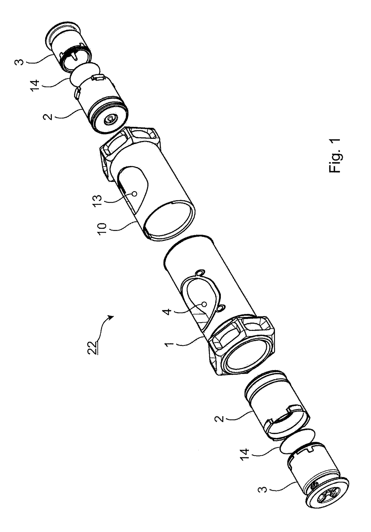
[0091]FIG. 1 shows an exploded view of a mixing capsule 22 according to the invention.

[0092]Mixing capsule 22 comprises a capsule body 10, a sleeve 11, two piston bodies 2 each having associated pistons 3, which for their part are each provided with a film 14.

[0093]Capsule body 1 has a substantially cylindrical shape, with sleeve 10 substantially enclosing capsule body 1 in operation. Piston bodies 2 are inserted into the initially open ends of the capsule body, a piston 3 sealed with a film 14 on the side facing piston body 2 being provided in each piston body.

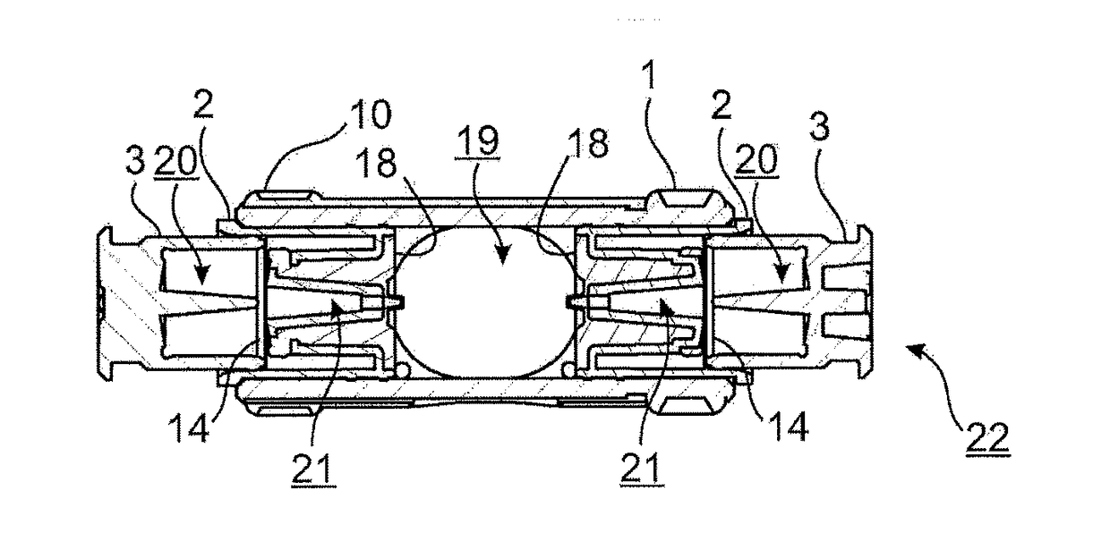
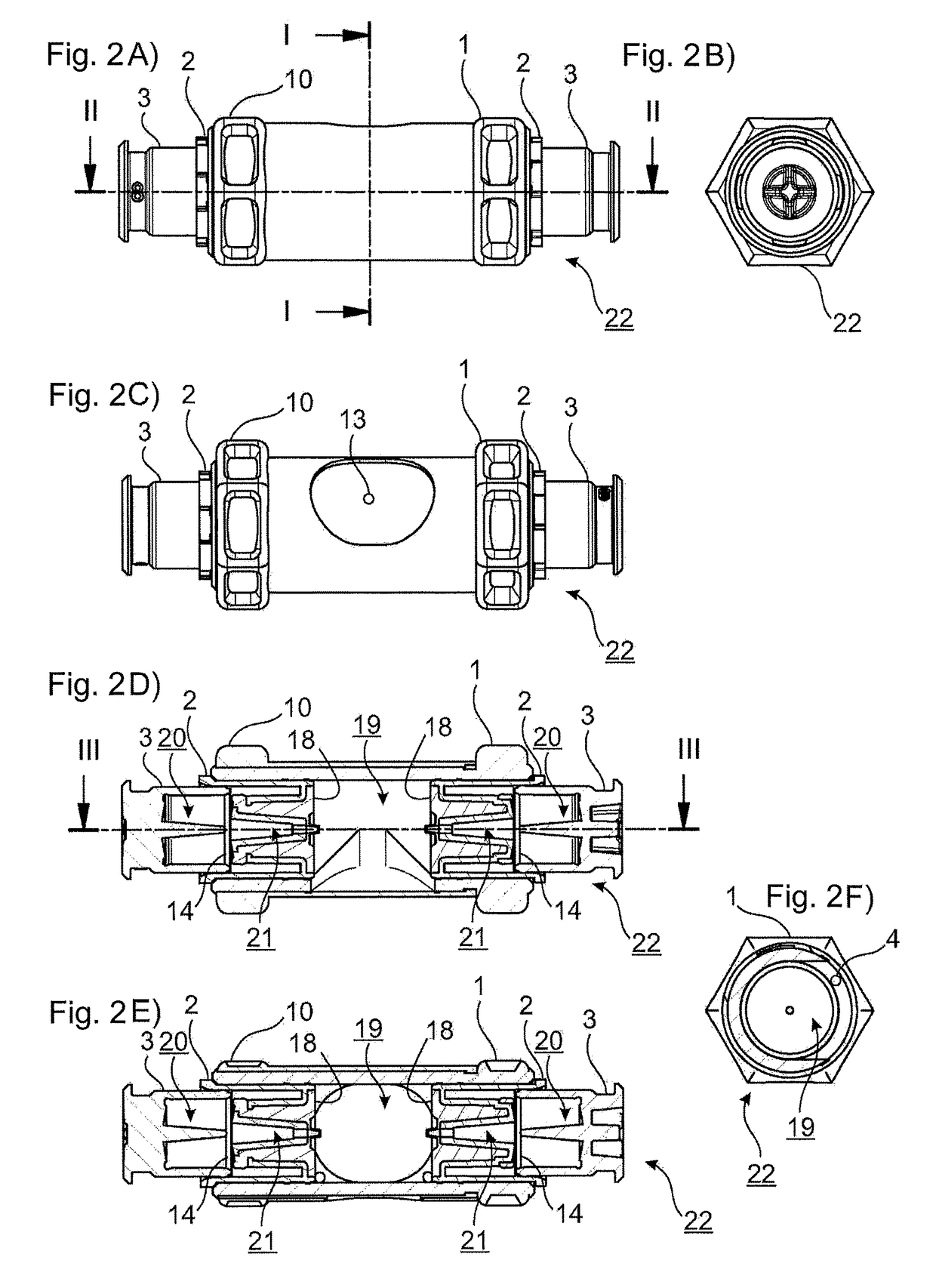
[0094]FIGS. 2A through 2F shows views and cross-sections of the mixing capsule 22 according to the first embodiment.

[0095]FIG. 2A shows a side view of mixing capsule 22 with sleeve 10 pushed onto capsule body 1. Piston bodies 2 have each been inserted into capsule body 1, and pistons 3 have been inserted slightly into piston bodies 2.

[0096]In FIG. 2A, two sectional planes are marked, sectional plane I corresponding to the vie...

second embodiment

[0127]FIGS. 10A through 10B show views and a cross-section of a mixing capsule 23 according to the invention.

[0128]As in the first embodiment, there is a substantially cylindrical capsule body into which piston bodies and pistons are inserted.

[0129]Unlike the first embodiment, however, this embodiment does not have a sleeve. Instead, the outlet opening of the mixing chamber is formed by an application cannula 16, which is closed by means of a closure means 15 so that, until closure means 15 is removed, the mixing chamber is hermetically closed by the capsule body and the piston bodies, at least to the extent that no undesired external influences can reach the mixing chamber. As in the first embodiment also, vent holes (not shown) may be provided in order to release any gases that are produced during mixing and possible reaction of the mixing components.

[0130]FIGS. 11A through 11D shows views and a cross-section of a mixing capsule 24 according to a third embodiment of the invention....

fourth embodiment

[0139]FIGS. 13A and 13B show views of mixing capsule 25 in an initial state and in a state after the mixed dental material has been expelled.

[0140]This view of the initial state corresponds to the views shown in FIGS. 12A through 12B from a different angle of vision. In the view of the state after expulsion of the mixed dental material, it can be seen that arm 26 now extends over the outer wall of capsule body 1 after being guided by ramp 28.

[0141]It is also possible that, instead of ramp 28, a groove (not shown) be provided in the outer wall of the capsule body, into which the arm can enter.

[0142]FIGS. 14A through 14E partly show views and partly show cross-sections of mixing capsule 25 according to the fourth embodiment, illustrating step by step how the mixing capsule is used.

[0143]FIG. 14A shows the initial state in which pistons 3 are inserted only a little into piston bodies 2, 2′, and the fluids (not shown) accommodated in pistons 3 are tightly sealed into pistons 3 by a res...


PUM


Abstract

In order to develop mixing and application capsules known from the prior art, so that limitations regarding the dental preparations that can be obtained are overcome, a mixing capsule (22) for producing a dental preparation is proposed in which the mixing capsule (22) has: a capsule body (1) having a mixing chamber for receiving a mixing component and for mixing the dental preparation from the mixing component, a first fluid and a second fluid and having an outlet opening (4) for expelling the dental preparation, a first cavity for receiving the first fluid, a first piston body (2) which delimits the mixing chamber in the capsule body (1) and which has a first passageway for guiding the first fluid from the first cavity into the mixing chamber, a second cavity for receiving the second fluid and a second piston body (2) which delimits the mixing chamber in the capsule body (1) and which has a second passageway for guiding the second fluid from the second cavity into the mixing chamber.

Description

CROSS REFERENCE TO RELATED APPLICATIONS[0001]This application claims priority to German Patent Application No. 102015200424.4, filed Jan. 14, 2015, the entire contents of which are incorporated herein by reference.BACKGROUND OF THE INVENTION[0002]The present invention relates to a mixing capsule for producing a dental preparation, the dental preparation being mixed from different components in a mixing chamber of the mixing capsule, which is securely positioned inside the mixing capsule until mixing.[0003]The expression “dental preparation” refers here to multi-component materials such as adhesives, filling materials, fixing materials in general (fixing cements in particular) and glass ionomers, but not to amalgams or amalgam mixtures. The invention is firstly aimed at providing a mixing capsule, but one which, in addition to its function as a “mixing capsule”, can also be used in certain circumstances as an application capsule.[0004]Mixing capsules which can also be used as applica...

Claims


Application Information

Patent Timeline
Patent Type & Authority Patents(United States)
IPC IPC(8): A61C19/00B01F13/00A61C5/66B05B11/00B05B11/02B01F15/02A61C5/64
CPCA61C5/66A61C5/64A61C19/005B01F13/0022B05B11/02B01F15/0223B01F15/0237B05B11/0081B01F15/0212B01F33/50111B01F35/7137B01F35/7161B01F35/7174
Inventor PLAUMANN, MANFRED THOMASBARG, ANDREELEINER, UWE
Owner VOCO
Why Eureka
Try Eureka