Sheet reversing device

a reverse device and sheet technology, applied in the direction of pile separation, article separation, transportation and packaging, etc., can solve the problems of affecting the operation of the machin

Inactive Publication Date: 2014-12-02
KOMORI CORP
View PDF16 Cites 1 Cited by
  • Summary
  • Abstract
  • Description
  • Claims
  • Application Information

AI Technical Summary

Benefits of technology

[0004]It is an object of the present invention to propose a sheet reversing device which can reliably turn a sheet with high accuracy despite its simple arrangement.
[0006]According to the present invention, when the third holder of the third conveyance unit holds the trailing edge of the sheet conveyed while its leading edge is held by the first holder of the first conveyance unit, the trailing edge of the sheet is pressed by the pressing member. With this operation, the trailing edge of the sheet can be prevented from fluttering to transfer the sheet to the second conveyance unit while the trailing edge of the sheet is reliably held by the third holder.

Problems solved by technology

However, this arrangement is complicated as it requires an air device formed by, for example, an air source, pipe, and nozzle for air discharge or suction.
This arrangement also requires adjusting the air pressure in accordance with, for example, the material of a sheet, and therefore imposes a heavy burden on the operator.
In this case, if the air pressure is not adjusted, the position at which the sheet is held by the reversing unit shifts to degrade the front and back registration accuracy, or the trailing edge of the sheet cannot be held to cause a conveyance failure.
Such a problem is posed not only in the printing press but also in processing machines which process the sheet, such as a coating machine and inspection machine.

Method used


Image

  • Sheet reversing device
  • Sheet reversing device
  • Sheet reversing device

Examples


Embodiment Construction

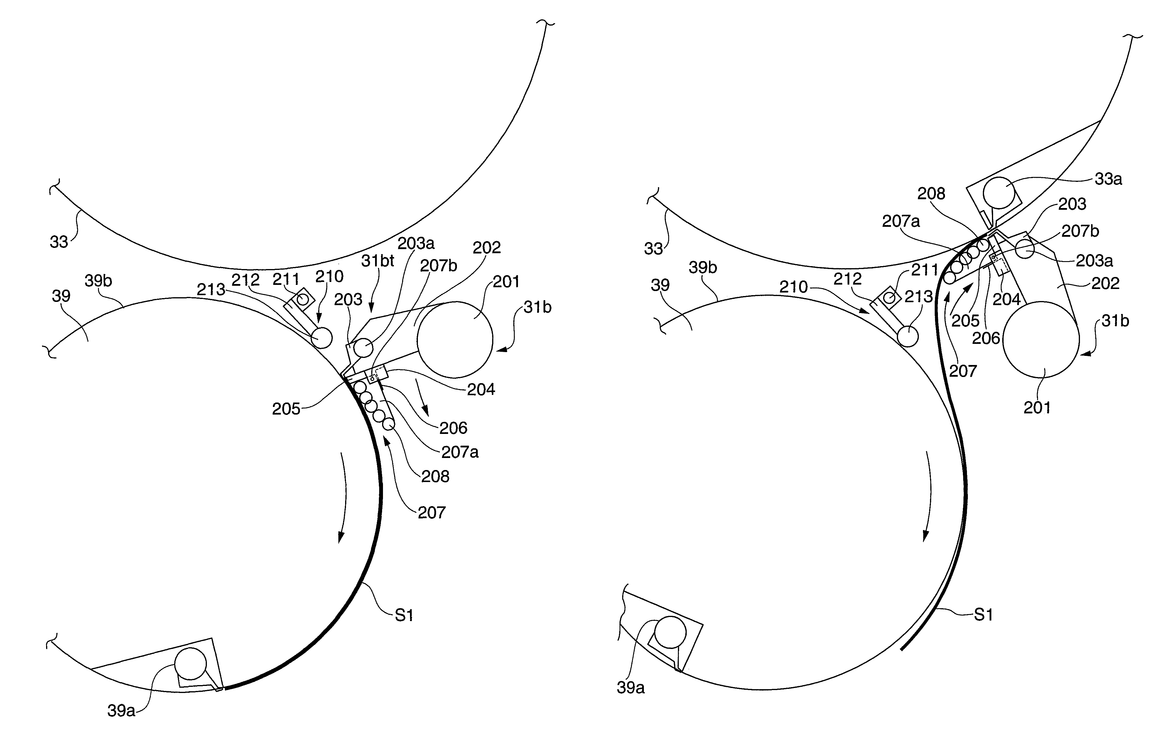
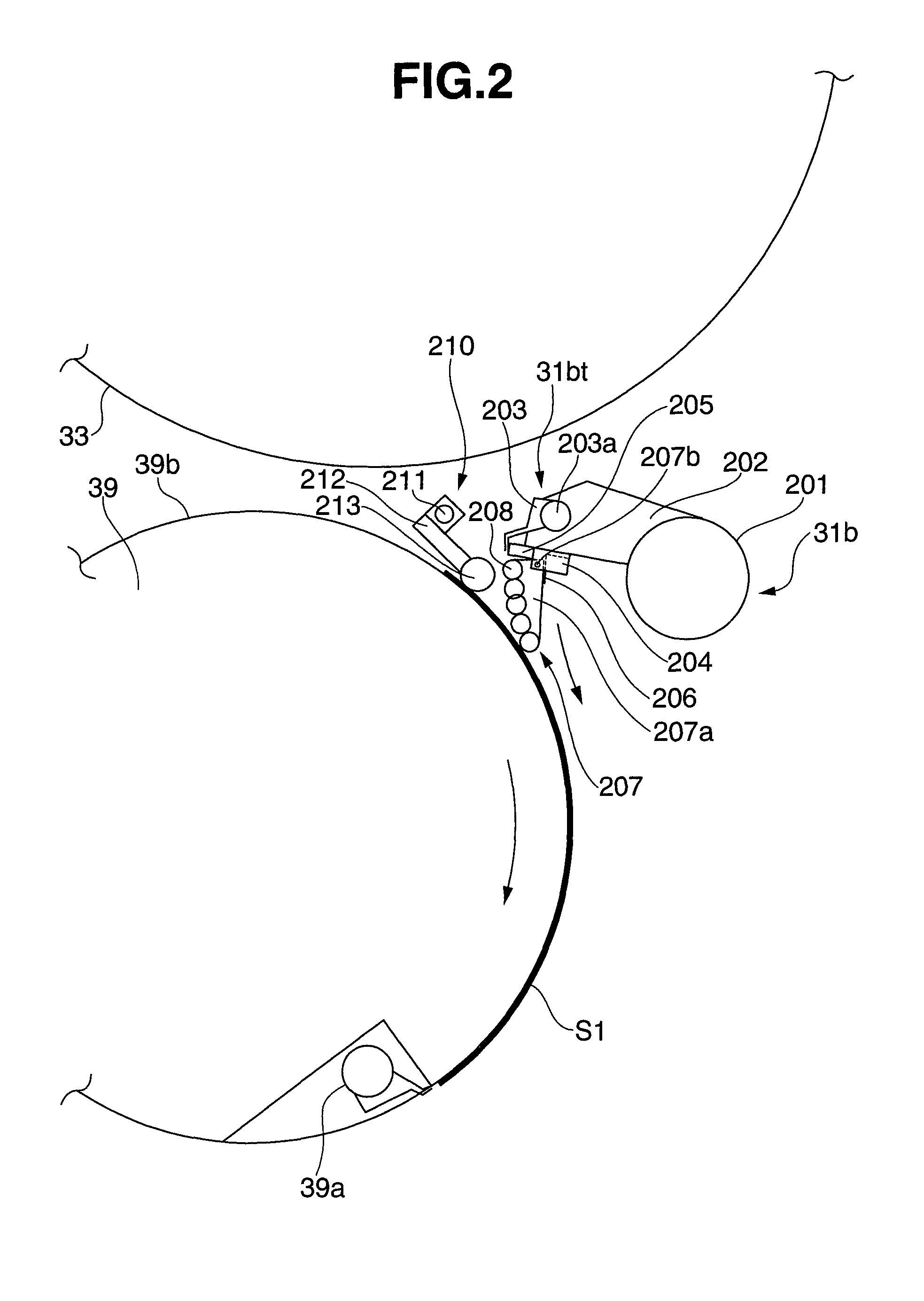
[0012]The present invention will be described in detail below with reference to the accompanying drawings.

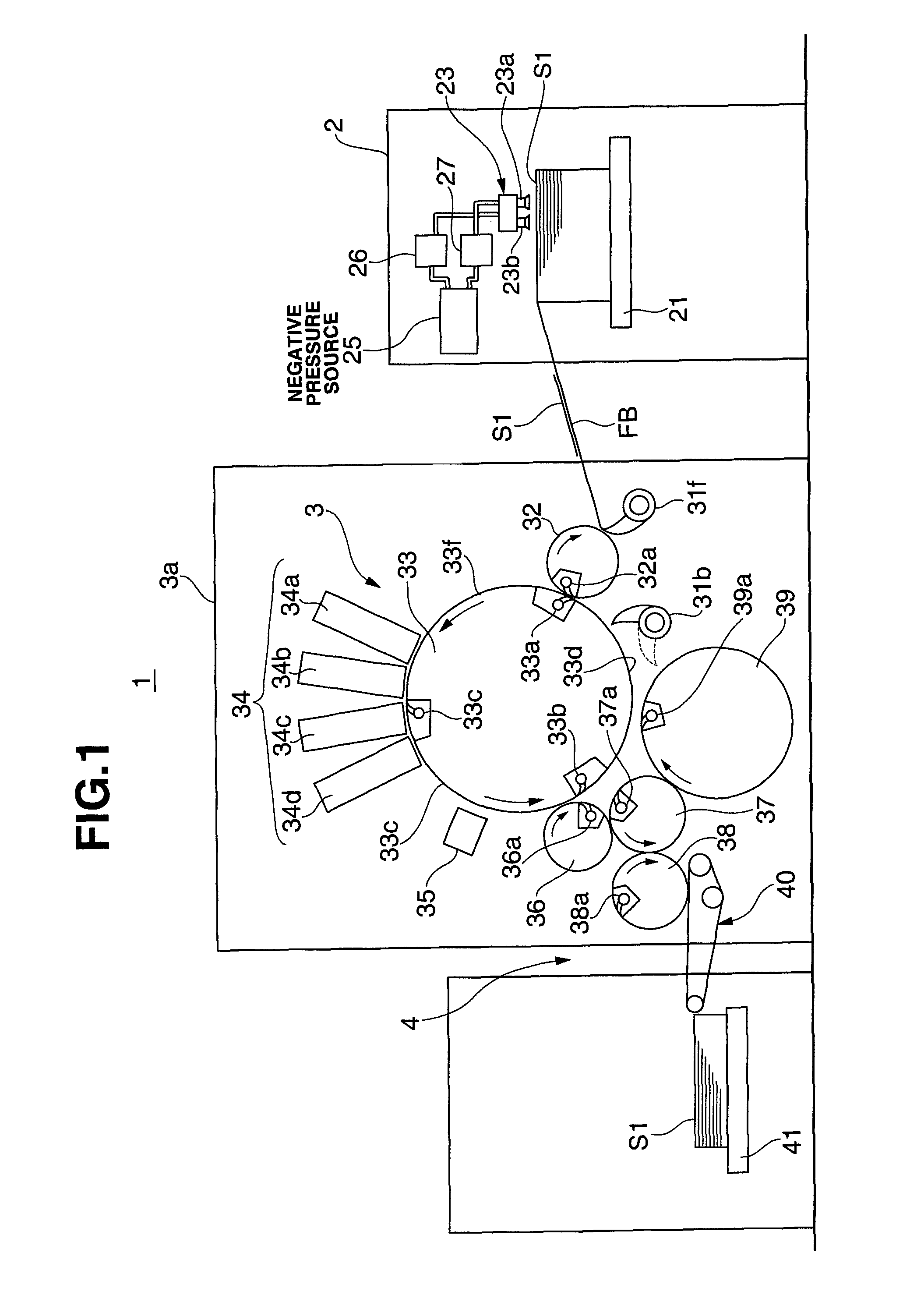
[0013]A digital printing apparatus 1 (sheet processing apparatus) according to this embodiment includes a sheet feed device 2 (sheet supply device), a digital printing unit 3 (processing unit), and a sheet delivery device 4 (sheet discharge device), as shown in FIG. 1.

[0014]The sheet feed device 2 includes a pile board 21 on which a plurality of sheets S1 are stacked, and a sucker device 23 which conveys the top sheet S1 on the pile board 21 onto a feeder board FB. The sucker device 23 includes a pair of suction ports 23a and 23b, which are connected to a negative pressure source 25 via a continuous supply valve 26 and an intermittent supply valve 27.

[0015]The continuous supply valve 26 and intermittent supply valve 27 enable / disable, at different timings, the suction operation of the suction ports 23a and 23b using a negative pressure from the negative pressure source 25.

[0016]...


PUM


Abstract

A sheet reversing device including a first conveyance unit, second conveyance unit, third conveyance unit, and sheet pressing member. The first conveyance unit includes a first holder, and a support surface that supports the sheet, and conveys the sheet with an edge held by the first holder, and its entire surface supported by the support surface. The second conveyance unit includes second holders, which convey the sheet. The third conveyance unit is supported to be swingable between a reception position at which the third conveyance unit receives the sheet, and a transfer position at which the third conveyance unit transfers the sheet to the second conveyance unit. The third conveyance unit includes a third holder, and conveys the sheet held by the third holder. The sheet pressing member presses the sheet, transferred from the third conveyance unit to the first conveyance unit, against the first conveyance unit support surface.

Description

BACKGROUND OF THE INVENTION[0001]The present invention relates to a sheet reversing device which turns a sheet.[0002]Conventionally, as an example of a sheet reversing device which turns a sheet, a sheet reversing unit applied to a sheet-fed offset rotary printing press equipped with a reversing mechanism, which is capable of printing on one or both of the two surfaces of a sheet, has been proposed, as described in Japanese Patent Laid-Open No. 58-219058. Such a conventional reversing unit is interposed between first and second, adjacent printing units, and performs a selective reversing operation for a sheet to allow single-sided printing and double-sided printing on the sheet.[0003]The conventional sheet-fed offset rotary printing press equipped with a reversing mechanism uses air blowing or suction to prevent the trailing edge of a sheet from fluttering in holding it by a reversing unit. However, this arrangement is complicated as it requires an air device formed by, for example,...

Claims


Application Information

Patent Timeline
Patent Type & Authority Patents(United States)
IPC IPC(8): B65H85/00B41J3/60B41F21/10B65H29/54B41J13/22
CPCB41J3/60B41J13/223B41F21/108B41F21/102B65H85/00B41F21/104
Inventor KONDO, HAYATOOGAWA, NAOKI
Owner KOMORI CORP
Why Eureka
Try Eureka