Method for improving safety of voltage regulator

a voltage regulator and safety technology, applied in the field of voltage regulators, can solve the problems of switching element generating a large amount of heat, affecting the safety of the voltage regulator, so as to prevent smoking and burning

Active Publication Date: 2019-01-10
LENOVO PC INT
View PDF2 Cites 2 Cited by
  • Summary
  • Abstract
  • Description
  • Claims
  • Application Information

AI Technical Summary

Benefits of technology

[0012]In accordance with a preferred embodiment of the present invention, a power-supply system includes a protection switch disposed on a power lane receiving power supply from a DC power supply, a group of voltage regulators, each having a switching element and branching off from the power lane, a temperature sensor for detecting temperature of the voltage regulators, and a controller for turning the protection switch OFF when temperature at any one of the voltage regulators increases and stops power supplied to the group of voltage regulators. With this configuration, if the switching element fails due to resistance short-circuit, the protection switch can be turned OFF in response to the detection of temperature such that smoking and burning can be prevented.
[0013]When the switching element is incorporated into a semiconductor chip, the temperature sensor can detect temperature at a surface or vicinity of the semiconductor chip. Temperature is detected from the outside of the semiconductor chip, whereby the temperature sensor is not affected from a sudden increase in temperature, if any, and can turn the protection switch OFF reliably. The temperature sensor may include a PTC thermistor. When temperature detected by the temperature sensor incorporated in the semiconductor chip increases, the controller can turn the protection switch OFF.
[0014]A temperature sensor for detecting temperature outside of the semiconductor chip, and a temperature sensor for detecting temperature inside thereof are provided, whereby reliable protection can be provided even when the switching element generates heat suddenly. When ON resistance or OFF resistance of the switching elements calculated from voltage and current increases, the voltage regulators may send a signal to turn the protection switch OFF to the controller. The present invention is suitable for the case where the group of voltage regulators include a first voltage regulator and a second voltage regulator that output mutually different voltages, and loads of the voltage regulators include a device that operates with output voltage from the first voltage regulator and output voltage from the second voltage regulator. With this configuration, if abnormality occurs at any one of the voltage regulators, all of the voltage regulators stop, and so latch up of the device as a load can be prevented.

Problems solved by technology

In the power-supply system of FIG. 7; however, the VRs 511a to 511c may cause smoking and burning.
Investigations on such a phenomenon show that a switching element burns severely.
A direct cause of the burning of a switching element results from the element generating a large amount of heat due to large current.
If a switching element in the close state fails, short-circuit current flowing will cause burnout of any one of the fuses 509a to 509c. However, smoking or burning generated means that the fuses 509a to 509c do not melt, or the timing of the melting, if any, may not work together with the circuit.
Such a current value and energizing time are sufficient to cause smoking and burning at the switching elements.
If a switching element burns while generating heat severely, all of the devices around it may be damaged or a normal sub-system also has to be replaced in some cases.
Further, if a switching element generates heat, it causes the risk of fire, and so it is not favorable to leave such a situation unsolved even when the risk is small.
Another problem occurs, which results from the loads 513a to 513c including a device that receives power from VRs 511a to 511c. For instance, when the load 513b includes a device receiving power from the VR 511a as well, and if the fuse 509a is molten, the device receives power continuously from the VR 511b in spite of stopping of the power-supply from the VR 511a. Then the device of the load 513b generates latch up, which increases the risk leading to secondarily generated smoking and burning.

Method used


Image

  • Method for improving safety of voltage regulator
  • Method for improving safety of voltage regulator
  • Method for improving safety of voltage regulator

Examples


Embodiment Construction

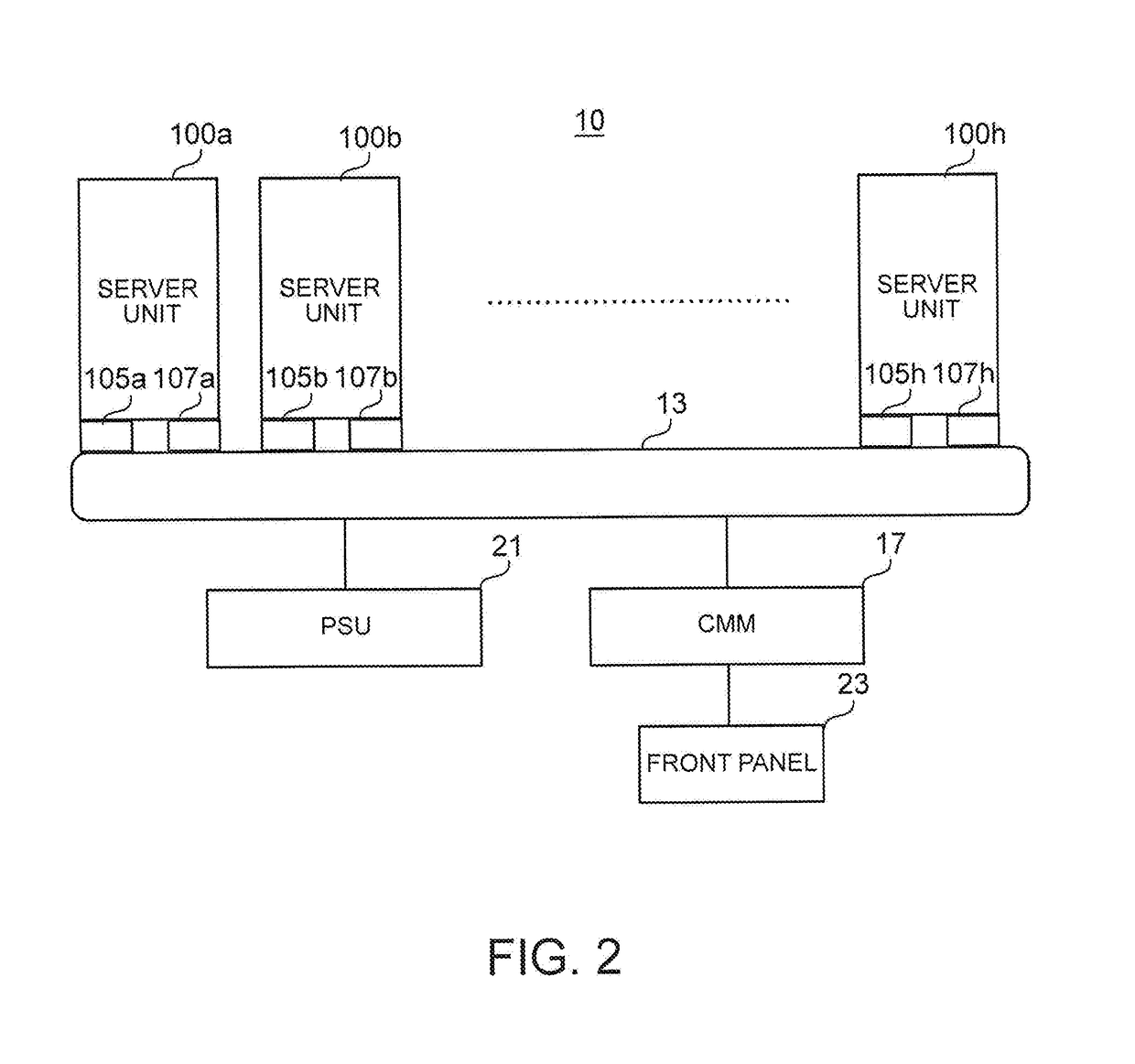
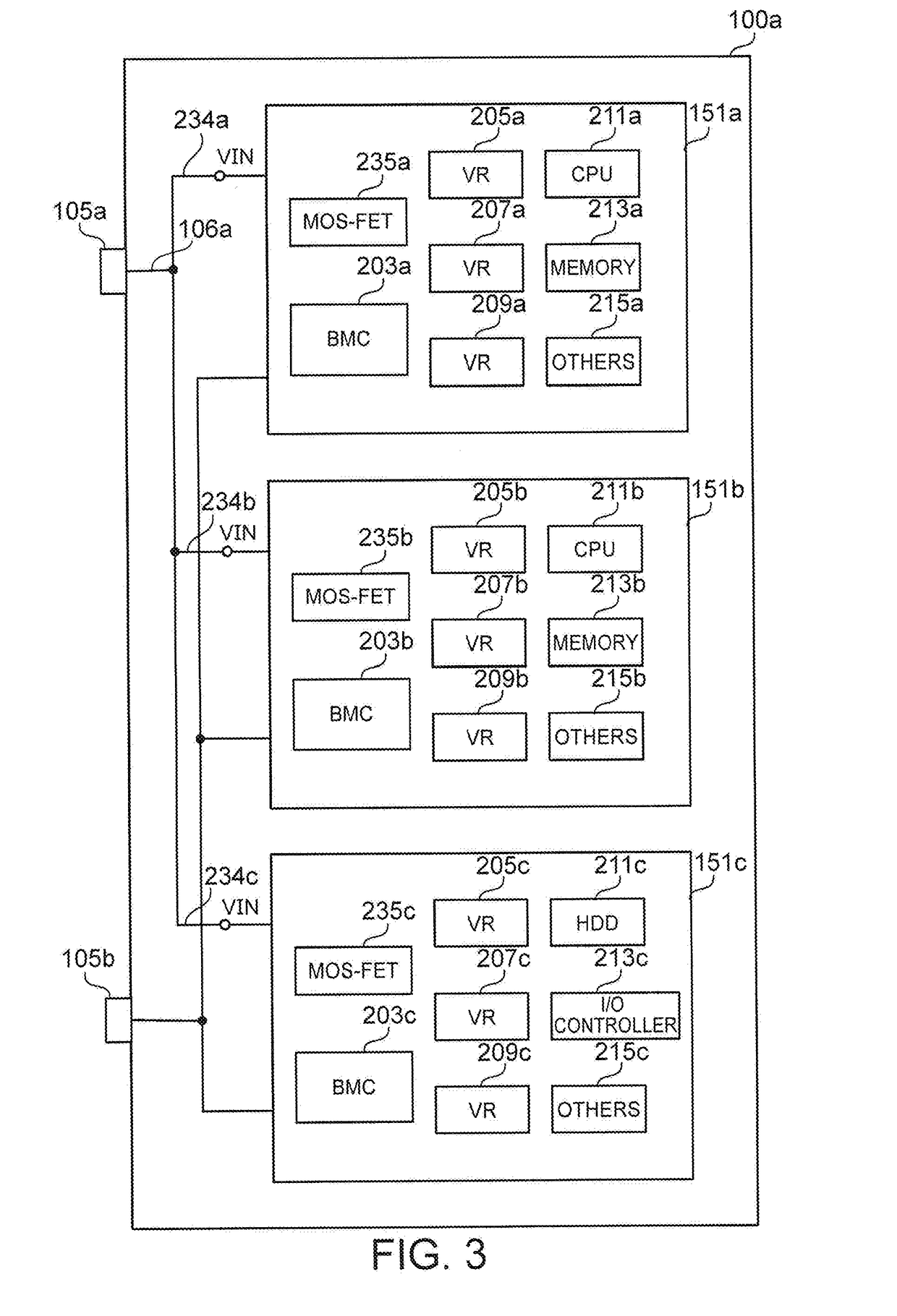
[0024]A power-supply system according to the present invention preferably is applicable to a set-type computer system. A set-type computer system includes a group of computer units, each having an equivalent computer function. Each computer unit includes hardware such as a processor, a system memory, an input / output (I / O) controller, a memory and a peripheral device, and software such as an operating system and an application program.

[0025]Each computer unit receives power from a power-supply unit (PSU) that converts utility power to DC voltage. Only one PSU may be provided for the computer system, or one PSU may be provided for a group of a plurality of computer units. Each computer unit includes a group of sub-systems. Each sub-system includes a group of voltage regulators (VRs). The set-type computer system may be implemented as a rack-mountable server, a blade server, a router or the like.

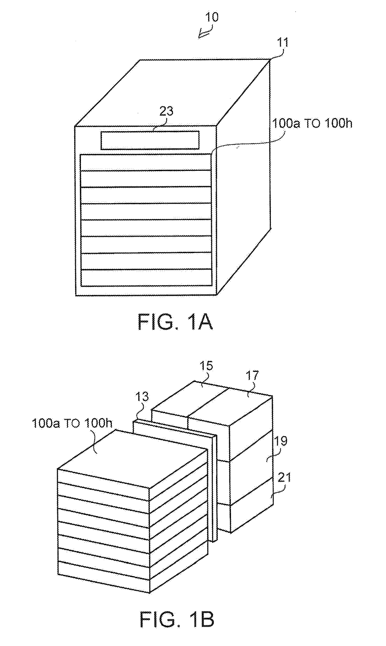
[0026]FIGS. 1 to 3 describe the outline of a blade server 10. FIG. 1A illustrates the outsi...


PUM


Abstract

A method for improving safety of voltage regulator is disclosed. In order to improve safety of a voltage regulator, a MOS-FET is disposed on a source power lane that receives power supplied from a DC power supply. A set of voltage regulators is connected to a set of fork power lanes, correspondingly, branching off from the source power lane. PTC thermistors are disposed on a surface or in the vicinity of semiconductor chips of the voltage regulators. When temperature at any one of the PTC thermistors increases, a protection controller turns off the MOS-FET. When temperature detected by a temperature sensor incorporated within the semiconductor chip has increased, each of the voltage regulators turns off the MOS-FET via a base management controller.

Description

PRIORITY CLAIM[0001]The present application claims benefit of priority under 35 U.S.C. §§ 120, 365 to the previously filed Japanese Patent Application No. JP2014-122932 with a priority date of Jun. 14, 2014, which is incorporated by reference herein.BACKGROUND OF THE INVENTION1. Technical Field[0002]The present invention relates to voltage regulators in general, and particularly to a method for improving the safety of a voltage regulator having a switching element, and to a method for preventing smoking and burning of a switching element.2. Description of Related Art[0003]FIG. 7 describes the outline of a typical power-supply system used for a server. A power-supply unit (PSU) 501 supplies power to a group of sub-systems 503 to 507 making up a server with DC voltage. Each sub-system 503 to 507 is mainly made up of voltage regulators (VRs) 511a to 511c that convert the output voltage of the PSU 501 to predetermined voltage and loads 513a to 513c corresponding to the VRs, such as a ce...

Claims


Application Information

Patent Timeline
Patent Type & Authority Applications(United States)
IPC IPC(8): H02H3/08H02H9/00H02H5/04
CPCH02H9/001H02H5/042H02H5/041H02H3/085
Inventor ODAOHHARA, SHIGEFUMIHINKLE, JONATHAN RANDALL
Owner LENOVO PC INT
Why Eureka
Try Eureka