
Dynamic optimization of beamforming weights

a beamforming weight and dynamic optimization technology, applied in the direction of spatial transmit diversity, electrical apparatus, diversity/multi-antenna systems, etc., can solve the problems of not being able to dynamically vary the bf value, the historic approach no longer satisfies the needs of a wireless telecommunications network moving forward, and the various embodiments of the historic approach cannot be realized. to achieve the effect of facilitating dynamic beamforming of telecommunications networks and altering the coverage footprin

Active Publication Date: 2019-01-01
T MOBILE INNOVATIONS LLC
View PDF2 Cites 14 Cited by
  • Summary
  • Abstract
  • Description
  • Claims
  • Application Information

AI Technical Summary

Benefits of technology

The patent text describes a technology that allows for dynamic beamforming in wireless networks. This technology uses multiple antennas to control the direction of a wavefront by appropriately weighting the amplitude and phase of individual antenna signals. By dynamically setting beamforming weights for antennas based on actual user equipment needs and demands, the technology can create an optimal broadcast beam for each UE. This can improve the efficiency and reliability of wireless networks as they move forward. The patent also describes methods for detecting and analyzing radio frequency markers from user equipment and using them to generate and apply beamforming weights to at least one telecommunications antenna.

Problems solved by technology

However, historically, these weights have been applied based on an initial coverage analysis of the area served by the telecommunications antenna and there was no possibility to dynamically vary the BF values based on different radio frequency (RF) or network connection conditions.
While this historic approach was sufficient to produce a wireless telecommunications network capable of providing service to the relatively small number of UEs, the historic approach no longer satisfies the needs of a wireless telecommunications network moving forward.
Further, the components, modules, processors, programs, and computers used to facilitate this historic approach to telecommunications networks could not function in the various embodiments described herein.

Method used


Image

  • Dynamic optimization of beamforming weights
  • Dynamic optimization of beamforming weights
  • Dynamic optimization of beamforming weights

Examples


Embodiment Construction

[0017]The subject matter of the technology described herein is described with specificity to meet statutory requirements. However, the description itself is not intended to limit the scope of this patent. Rather, the inventors have contemplated that the claimed subject matter might also be embodied in other ways, to include different steps or combinations of steps similar to the ones described in this document, in conjunction with other present or future technologies. Moreover, although the terms “step” and / or “block” may be used herein to connote different elements of the methods employed, the terms should not be interpreted as implying any particular order among or between various steps herein disclosed unless and except when the order of individual steps is explicitly described.

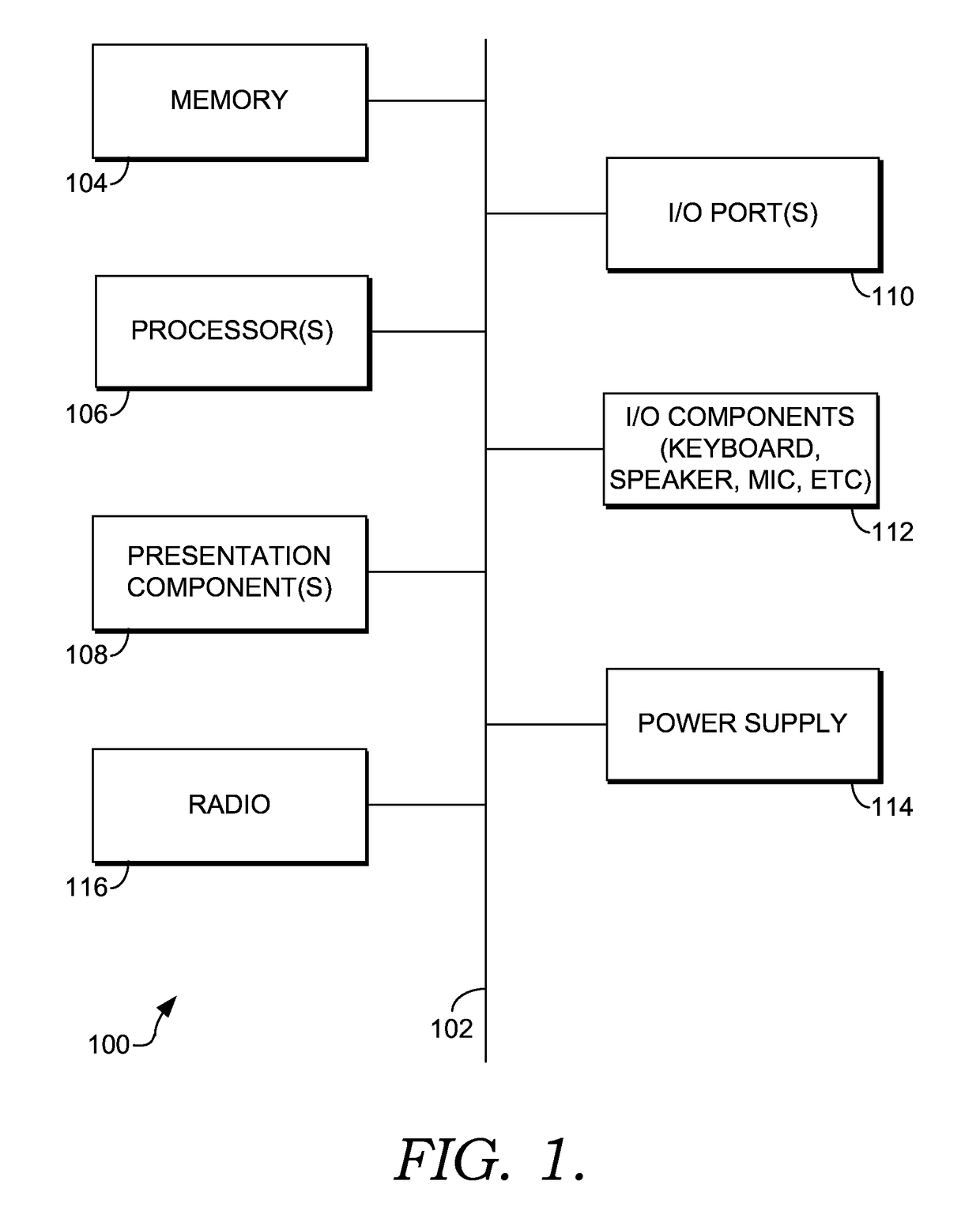
[0018]With reference to FIG. 1, computing device 100 includes a bus 110 that directly or indirectly couples the following devices: memory 112, one or more processors 114, one or more presentation component...


PUM


Abstract

Dynamic beamforming in a telecommunications network in response to communication parameters is described. The communication parameters may be associated with at least one user device and / or at least one antenna. For example, the communication parameters may include CQI (channel quality indicator), SINR (signal-to-noise ratio), location data, channel load, sector load, band load, front-to-back ratio (F / B ratio), and / or upper side lobe suppression (USLS). The communication parameters may trigger generation of new beamforming weights and application of the new beamforming weights to the telecommunications network.

Description

BRIEF SUMMARY[0001]A high-level overview of various aspects of the technology described herein is provided as an overview of the disclosure and to introduce a selection of concepts that are further described in the detailed-description section below. This summary is not intended to identify key features or essential features of the claimed subject matter, nor is it intended to be used as an aid in isolation to determine the scope of the claimed subject matter.[0002]Generally beamforming uses multiple antennas to control the direction of a wavefront by appropriately weighting the amplitude and phase of individual antenna signals. Beamforming is made possible by weighting the amplitude and or phase of the signal broadcast at the individual antenna. Beamforming may further be made possible by weighting the tilt of the broadcasting antenna. The present disclosure is directed, in part, to dynamically setting beamforming weights for antennas serving a communications network, substantially...

Claims


Application Information

Patent Timeline
Patent Type & Authority Patents(United States)
IPC IPC(8): H04B1/00H04B7/0452H04B7/06H04B15/00H04B7/0426
CPCH04B7/0617H04B7/0626H04B7/0632H04B7/043H04B7/0452
Inventor MARUPADUGA, SREEKARWURTENBERGER, ANDREW M.
Owner T MOBILE INNOVATIONS LLC
Learn More