Method and apparatus for oil and gas operations

a technology for oil and gas operations, applied in the direction of earth drilling, wellbore/well accessories, sealing/packing, etc., can solve the problems of compromising the original design of the christmas tree, complex and carefully designed christmas tree equipment, and avoiding deviations in the location of critical components

Active Publication Date: 2019-01-08
ENPRO SUBSEA
View PDF59 Cites 11 Cited by
  • Summary
  • Abstract
  • Description
  • Claims
  • Application Information

AI Technical Summary

Benefits of technology

[0004]There are a number of reasons why it is desirable to access a flow system in an oil and gas production system. In the context of this specification, the term “fluid intervention” is used to encapsulate any method which accesses a flow line, manifold or tubing in an oil and gas production, injection or transportation system. This includes (but is not limited to) accessing a flow system for fluid sampling, fluid diversion, fluid recovery, fluid injection, fluid circulation, fluid measurement and / or fluid metering. This can be distinguished from full well intervention operations, which generally provide full (or near full) access to the wellbore. Full well intervention processes and applications are often technically complex, time-consuming and have a different cost profile to fluid intervention operations. It will be apparent from the following description that the present invention has application to full well intervention operations. However, it is an advantage of the invention that full well intervention may be avoided, and therefore preferred embodiments of the invention provide methods and apparatus for fluid intervention which do not require full well intervention processes.
[0005]International patent application numbers WO00 / 70185, WO2005 / 047646, and WO2005 / 083228 describe a number of configurations for accessing a hydrocarbon well via a choke body on a Christmas tree.
[0006]Although a choke body provides a convenient access point in some applications, the methods of WO00 / 70185, WO2005 / 047646, and WO2005 / 083228 do have a number of disadvantages. Firstly, a Christmas tree is a complex and carefully-designed piece of equipment. The choke performs an important function in production or injection processes, and its location on the Christmas tree is selected to be optimal for its intended operation. Where the choke is removed from the choke body, as proposed in the prior art, the choke must be repositioned elsewhere in the flow system to maintain its functionality. This compromises the original design of the Christmas tree, as it requires the choke to be located in a sub-optimal position.
[0007]Secondly, a choke body on a Christmas tree is typically not designed to support dynamic and / or static loads imparted by intervention equipment and processes. Typical loads on a choke body in normal use would be of the order of 0.5 to 1 tonnes, and the Christmas tree is engineered with this in mind. In comparison, a typical flow metering system as contemplated in the prior art may have a weight of the order of 2 to 3 tonnes, and the dynamic loads may be more than three times that value. Mounting a metering system (or other fluid intervention equipment) on the choke body therefore exposes that part of the Christmas tree to loads in excess of those that it is designed to withstand, creating a risk of damage to the structure. This problem may be exacerbated in deepwater applications, where even greater loads may be experienced due to thicker and / or stiffer components used in the subsea infrastructure.
[0008]In addition to the load restrictions identified above, positioning the flow intervention equipment on the choke body may limit the access available to large items of process equipment and / or access of divers or remotely operated vehicles (ROVs) to the process equipment or other parts of the tree.
[0009]Furthermore, modifying the Christmas tree so that the chokes are in non-standard positions is generally undesirable. It is preferable for divers and / or ROV operators to be completely familiar with the configuration of components on the Christmas tree, and deviations in the location of critical components are preferably avoided.

Problems solved by technology

Full well intervention processes and applications are often technically complex, time-consuming and have a different cost profile to fluid intervention operations.
Firstly, a Christmas tree is a complex and carefully-designed piece of equipment.
This compromises the original design of the Christmas tree, as it requires the choke to be located in a sub-optimal position.
Secondly, a choke body on a Christmas tree is typically not designed to support dynamic and / or static loads imparted by intervention equipment and processes.
Mounting a metering system (or other fluid intervention equipment) on the choke body therefore exposes that part of the Christmas tree to loads in excess of those that it is designed to withstand, creating a risk of damage to the structure.
This problem may be exacerbated in deepwater applications, where even greater loads may be experienced due to thicker and / or stiffer components used in the subsea infrastructure.
In addition to the load restrictions identified above, positioning the flow intervention equipment on the choke body may limit the access available to large items of process equipment and / or access of divers or remotely operated vehicles (ROVs) to the process equipment or other parts of the tree.
Furthermore, modifying the Christmas tree so that the chokes are in non-standard positions is generally undesirable.
Another drawback of the prior art proposals is that not all Christmas trees have chokes integrated with the system; approaches which rely on Christmas tree choke body access to the flow system are not applicable to these types of tree.

Method used


Image

  • Method and apparatus for oil and gas operations
  • Method and apparatus for oil and gas operations
  • Method and apparatus for oil and gas operations

Examples


Embodiment Construction

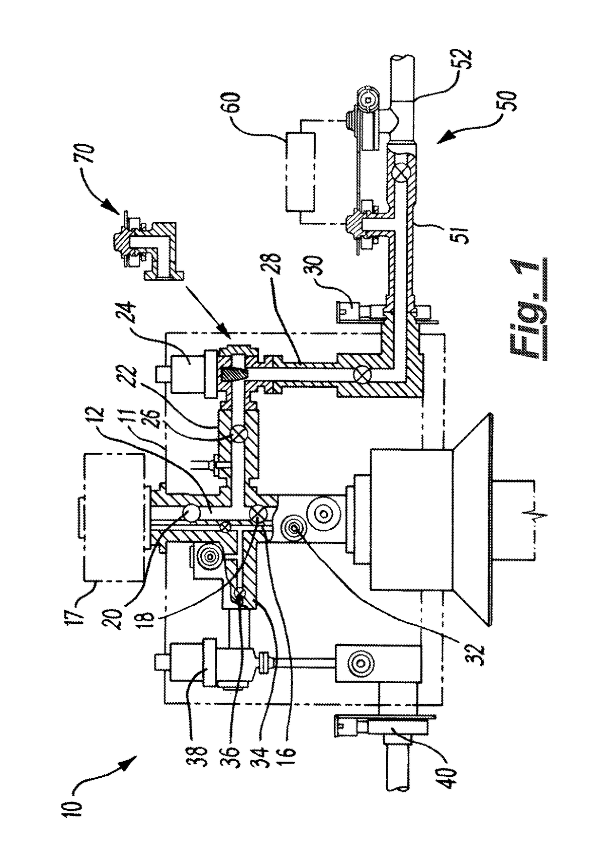
[0089]Referring firstly to FIG. 1, there is shown a production system generally depicted at 10, incorporating a subsea manifold in the form of a conventional vertical dual bore Christmas tree 11 located on a wellhead (not shown). The system 10 is shown in production mode, in a part-sectional view to show some external components from a side elevation and some parts of the system in longitudinal section. The tree 11 comprises a production bore 12 in communication with production tubing (not shown) and an annulus bore 16 in communication with the annulus between the casing and the production tubing. The upper part of the system 10 is closed by a conventional tree cap 17.

[0090]The production bore 12 comprises hydraulically controlled valves which include a production master valve 18 and a production swab valve 20 (as is typical for a vertical subsea tree). The production bore 12 also comprises a branch 22 which in includes production choke valve 24, and which may be closed from the bor...


PUM


Abstract

An apparatus and system for accessing a flow system (such as a subsea tree) in a subsea oil and gas production system, and method of use. The apparatus comprises a body defining a conduit therethrough and a first connector for connecting the body to the flow system. A second connector is configured for connecting the body to an intervention apparatus, such as an injection or sampling equipment. In use, the conduit provides an intervention path from the intervention apparatus to the flow system. Aspects of the invention relate to combined injection and sampling units, and have particular application to well scale squeeze operations.

Description

CROSS-REFERENCE TO RELATED APPLICATIONS[0001]This application is a National Stage Application of PCT / GB2013 / 050364, filed Feb. 15, 2013, which designates the United States and claims the priority of GB patent application GB1202581.3, filed on Feb. 15, 2012, the subject matter of which is incorporated herein by reference.[0002]The present invention relates to methods and apparatus for oil and gas operations, in particular to methods and apparatus for fluid intervention in oil and gas production or injection systems. The invention has particular application to subsea oil and gas operations, and aspects of the invention relate specifically to methods and apparatus for fluid intervention in subsea oil and gas production and injection infrastructure.BACKGROUND TO THE INVENTION[0003]In the field of oil and gas exploration and production, it is common to install an assembly of valves, spools and fittings on a wellhead for the control of fluid flow into or out of the well. A Christmas tree ...

Claims


Application Information

Patent Timeline
Patent Type & Authority Patents(United States)
IPC IPC(8): E21B33/076E21B49/00E21B49/08E21B33/038E21B33/035E21B34/04
CPCE21B33/076E21B33/035E21B49/08E21B34/04E21B49/001E21B33/038
Inventor DONALD, IANREID, JOHN
Owner ENPRO SUBSEA
Why Eureka
Try Eureka