
Current sensor abnormality diagnosis device

Active Publication Date: 2019-01-08
DENSO CORP
View PDF4 Cites 2 Cited by
  • Summary
  • Abstract
  • Description
  • Claims
  • Application Information

AI Technical Summary

Benefits of technology

The patent describes a device that can detect abnormalities in multiple current sensors used in a multi-phase alternating current motor. The device uses a computer system to compare the current in each phase with a threshold value. If the current exceeds the threshold, the device identifies which sensor is malfunctioning. The device can also detect if the sensor for the bus current is operating properly. This allows for timely detection and correction of any abnormalities in the current sensors, ensuring proper operation of the motor.

Problems solved by technology

However, it is difficult for the diagnosis device having the structure disclosed in the patent documents 1 and 2 to correctly specify the current sensor in abnormality when the output value of one of the three current sensors becomes an undefined value due to occurrence of a circuit short of a variable voltage or occurrence of a power source short.

Method used


Image

  • Current sensor abnormality diagnosis device
  • Current sensor abnormality diagnosis device
  • Current sensor abnormality diagnosis device

Examples


Embodiment Construction

[0028]Hereinafter, various embodiments of the present invention will be described with reference to the accompanying drawings. In the following description of the various embodiments, like reference characters or numerals designate like or equivalent component parts throughout the several diagrams.

Exemplary Embodiment

[0029]A description will be given of a current sensor abnormality diagnosis device according to an exemplary embodiment with reference to drawings.

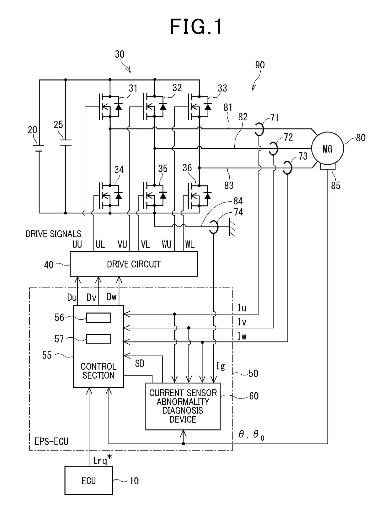
[0030]FIG. 1 is a view showing a schematic structure of a motor drive system 90 having a current sensor abnormality diagnosis device 60 according to an exemplary embodiment.

[0031]For example, it is possible to apply the current sensor abnormality diagnosis device 60 according to the exemplary embodiment to an electric power steering device having the motor drive system 90. The current sensor abnormality diagnosis device 60 detects occurrence of abnormality of phase current sensors 71-73. Each of the phase current sensors 71-7...


PUM


Abstract

In a current sensor abnormality diagnosis device, an abnormality judgment section determines that the phase current sensors are operating normally when a sum of three phase currents is not more than a threshold value, and a bus current sensor is operating normally based on a comparison result between three phase currents and a bus current. The abnormality judgment section detects which the phase current sensor has failed based on the three phase currents and the bus current when the sum of the three phase currents is more than the threshold value. Because of using the comparison results of the three phase currents with the bus current in addition to the sum of the three phase currents, it is possible for the abnormality judgment section to detect the occurrence of abnormality of each of these current sensors even if the detected current has an undefined value.

Description

CROSS-REFERENCE TO RELATED APPLICATION[0001]This application is related to and claims priority from Japanese Patent Application No. 2016-199161 filed on Oct. 7, 2016, the contents of which are hereby incorporated by reference.BACKGROUND OF THE INVENTION1. Field of the Invention[0002]The present invention relates to current sensor abnormality diagnosis devices for diagnosing abnormality of a current sensor.2. Description of the Related Art[0003]There has been known a conventional diagnosis device in a drive system to be applied to multi-phase alternating current motors of not less than three phases. Such a conventional diagnosis device is capable of diagnosing abnormality of each of multiple current sensors. The current sensors detect a current flowing in each phase.[0004]Patent documents 1 and 2, Japanese patent laid open publications No. 2009-131043 and H06-253585, have disclosed such a conventional diagnosis device having a structure which determines occurrence of abnormality of o...

Claims


Application Information

Patent Timeline
Patent Type & Authority Patents(United States)
IPC IPC(8): H02P27/00H02P21/18H02P6/17H02P6/12H02P21/22H02P27/08H02P25/14H02P23/14H02P29/68
CPCH02P6/12H02P6/17H02P21/18H02P29/68H02P23/14H02P25/145H02P27/085H02P21/22H02P27/08H02P29/0241
Inventor OKA, ATSUKOKURAMITSU, SHUJINAKAMURA, KOICHI
Owner DENSO CORP
Learn More