Luminaire for emitting directional and nondirectional light

a technology of directional and non-directional light and luminaire, which is applied in the field of illumination products, can solve the problems of increasing complexity and cost of the lighting system, inefficient operation of halogen lamps, and inconvenient use, so as to reduce the contrast between them, reduce the cost, and simplify the configuration of the luminaire.

Active Publication Date: 2019-01-15
AXIS LIGHTING +1
View PDF18 Cites 2 Cited by
  • Summary
  • Abstract
  • Description
  • Claims
  • Application Information

AI Technical Summary

Benefits of technology

[0008]Applicants recognize that by optically coupling a directional light-emitting element with a nondirectional light-emitting surface in a luminaire, both directional and nondirectional light can be can be emitted using the same light source(s). Such a configuration has a number of advantages. For example, such a luminaire configuration is simple, efficient, and cost effective because the same light source(s) can be used to emit both directional and nondirectional light. Additionally, because the different light-emitting surfaces / elements are optically coupled, the contrast between them is reduced, thereby reducing glare, and generally adding to the esthetics of the luminaire's illumination. Such a configuration also facilitates the use of other technologies for controlling, for example, the direction and color of the emitted light. For example the directional light may have one correlated color temperature (CCI) value and the non-directional light may have a different CCT value. Other features and advantages of the luminaire system of the present invention will be apparent to those of skill in the art in light of this disclosure.

Problems solved by technology

Specifically, a luminaire having high-intensity light can cause glare, owing to the stark contrast between the luminaire's high intensity light-emitting surface and the surface surrounding it.
This necessarily requires discrete lighting sources and driving circuitry, thus adding complexity and cost to the lighting system.
However, halogen lamps tend to be inefficient (e.g., about 10-20 lumens / W or about 5% of theoretical light-generation efficiency), and, thus are not cost effective to operate.

Method used


Image

  • Luminaire for emitting directional and nondirectional light
  • Luminaire for emitting directional and nondirectional light
  • Luminaire for emitting directional and nondirectional light

Examples


Embodiment Construction

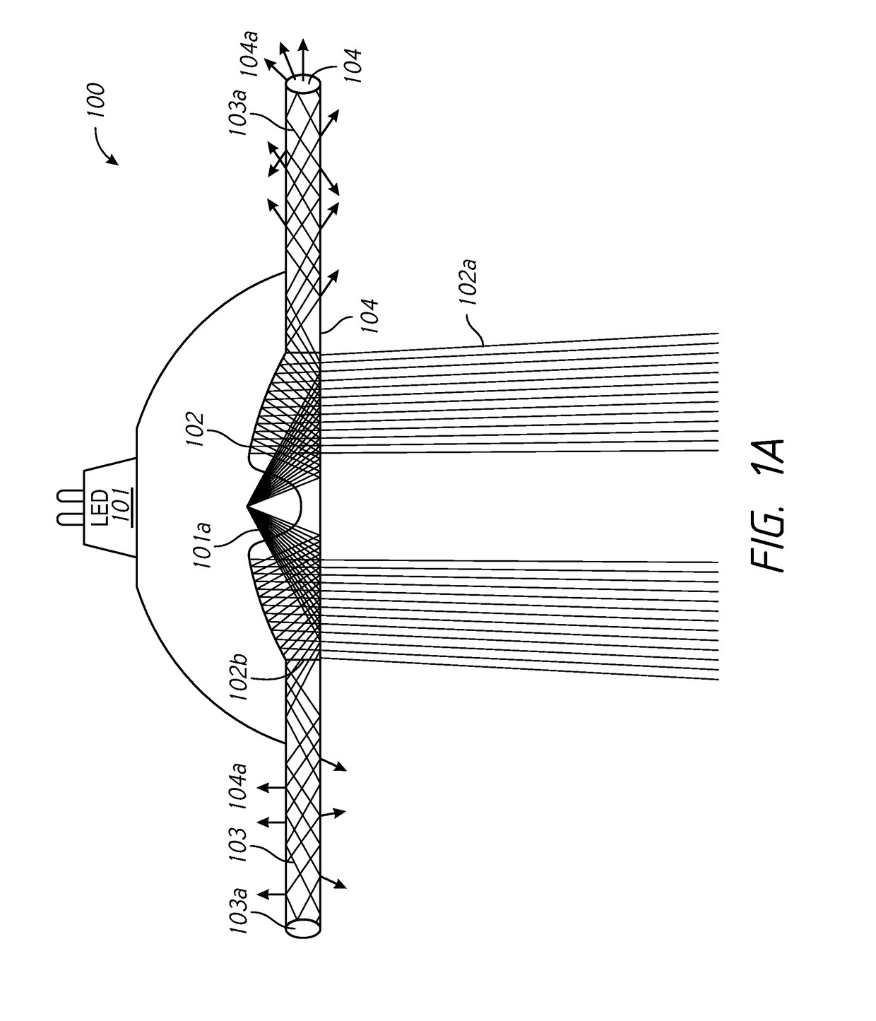
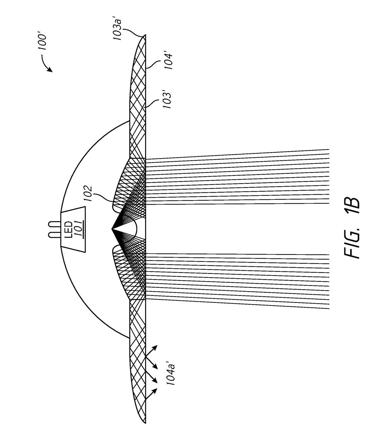
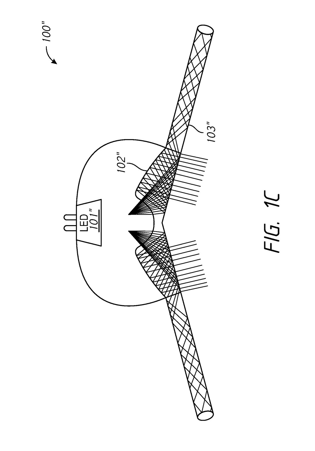
[0019]Referring to FIG. 1A, one embodiment of an light-emitting diode (LED) luminaire 100 of the present invention is shown. The luminaire 100 comprises (a) at least one LED light source 101 for emitting light rays 101a; (b) at least one directional light-emitting element 102 optically coupled to the at least one LED light source 101 to receive at least a portion of the light rays 101a and to emit directional light 102a from the luminaire; (c) at least one waveguide 103 optically coupled to the at least one LED light source 101 to receive at least a portion of the light rays 101a; and (d) at least one nondirectional light-emitting element 104 optically coupled to the at least one waveguide 103 and configured to emit non-directional light 104a. These elements and selected embodiments are described in greater detail below.

[0020]As used herein, and as understood in the art, directional light rays refers to light emission patterns having a distribution of intensity which is substantiall...


PUM


Abstract

An LED luminaire comprising: at least one directional light-emitting element configured to emit directional light from the luminaire; at least one nondirectional light-emitting element configured to emit non-directional light from the luminaire, the at least one nondirectional light-emitting element being optically coupled to the at least one directional light-emitting element; and at least one LED light source for emitting light and being optically coupled to at least one of the at least one directional light-emitting element or the at least one nondirectional light-emitting element.

Description

RELATED APPLICATION[0001]This application claims priority to U.S. Provisional Application No. 62 / 077,039, filed Nov. 7, 2014, incorporated herein by reference.FIELD OF DISCLOSURE[0002]This disclosure relates generally to the field of illumination products including luminaires, and, more particularly, to a luminaire for emitting directional and nondirectional light.BACKGROUND[0003]Many illumination applications (e.g., luminaires) require control of the light attributes (e.g., direction or intensity) for both functional and aesthetic purposes. For example, in a workroom, high-intensity light may be directed toward one or more specific work areas, while the room is illuminated diffusely. Likewise, in a conference room, light may directed toward the table area, while diffuse, ambient light illuminates the rest of the room.[0004]Beyond the need to provide both directional and ambient / diffuse light, Applicants recognize the need to provide ambient light along with direction light to reduc...

Claims


Application Information

Patent Timeline
Patent Type & Authority Patents(United States)
IPC IPC(8): F21V8/00F21S8/00F21S8/06F21Y105/00F21Y115/10
CPCG02B6/0001F21S8/00F21S8/06G02B6/0045F21Y2115/10G02B6/002F21Y2105/00
Inventor PARKER, JEFFERY ROBERTSHUM, FRANKSUN, YUPINPEIFER, DONYAPHE, HOWARDCALUORI, GIUSEPPEMILES, ANDREWMIER-LANGNER, ALEJANDRO
Owner AXIS LIGHTING
Why Eureka
Try Eureka