End cap for closing trunking for routing electrical conductors or cables

a technology of end caps and trunking, which is applied in the direction of electrical equipment, substation/switching arrangement details, connection contact material, etc., can solve the problems of not always easy to fit, difficult to fit, and difficult to fit end caps in two separate parts

a technology of end caps and trunking, which is applied in the direction of electrical equipment, substation/switching arrangement details, connection contact material, etc., can solve the problems of not always easy to fit, difficult to fit, and difficult to fit end caps in two separate parts

US20010025716A1Inactive Publication Date: 2001-10-04LEGRAND SNC

Image

  • End cap for closing trunking for routing electrical conductors or cables
  • End cap for closing trunking for routing electrical conductors or cables
  • End cap for closing trunking for routing electrical conductors or cables

Examples


Embodiment Construction

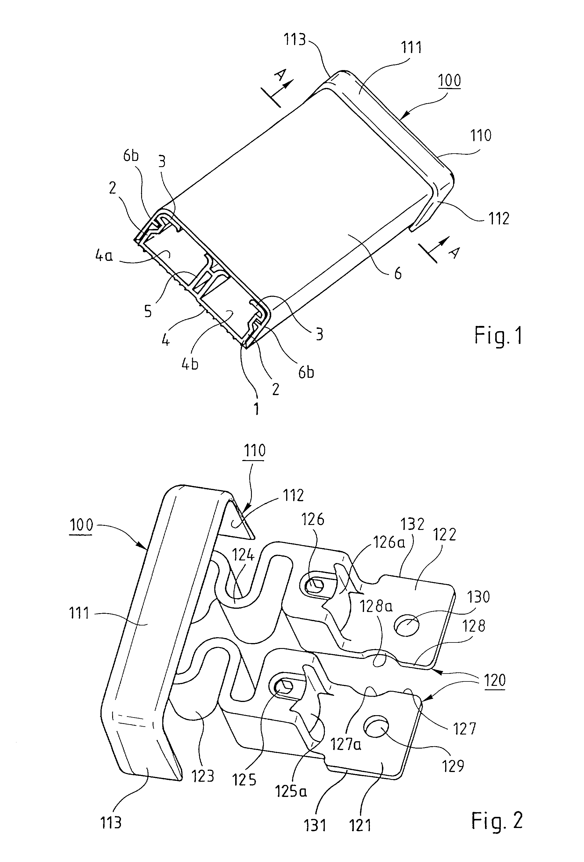
[0040] Note that identical or similar parts of the various embodiments of the invention are as far as possible designated by the same reference symbols in all the figures and are not described again each time. FIG. 1 shows trunking 1 with small dimensions, also referred to as a molding, designed for routing electrical cables or conductors.

[0041] The molding 1 includes a base section having a back 4 flanked by two longitudinal lateral flanges 2, this example of the base section having a generally U-shaped cross section. This is known in the art.

[0042] In this embodiment, the longitudinal lateral flanges 2 of the base section of the trunking have rims 3 facing toward each other in a plane substantially transverse to the lateral flanges 2.

[0043] The base section of the trunking is divided into two longitudinal compartments by a longitudinal central wall 5 having divergent rims at its free edge, each rim being directed toward the rim 3 of one longitudinal lateral flange 2 of the base se...


PUM


Abstract

An end cap for closing one end of trunking, the end cap having a closure part for closing an interior space of the trunking and a fixing part for fixing it to a back of a base section of the trunking. The closure and fixing parts are connected together by a connecting part. The connecting part constitutes an elastic coupling which allows the closure part to move relative to the fixing part.

Description

BACKGROUND OF THE INVENTION[0001] 1. Field of the Invention[0002] The present invention relates to an end cap for trunking of the type used, for example, to support, house and protect various devices, and in particular various electrical devices, and to support, house and protect electrical conductors or cables connected to those devices.[0003] 2. Description of the Prior Art[0004] The present invention relates more particularly to an end cap having a closure part for closing the interior space of the trunking and a fixing part for fixing it to the back of the base section of the trunking, the closure and fixing parts being connected together by a connecting part.[0005] An end cap of the above kind is designed to protect the end of the trunking against impact and, most importantly, to protect persons from the electrical cables or conductors inside the trunking.[0006] The two functions are combined when it is required to prevent the insertion of foreign bodies such as wires, pins or ...

Claims


Application Information

Patent Timeline
04 Oct 2001
Publication
US20010025716A1
IPC
H02G3/04
CPC
H02G3/0418
Inventors
BUARD, Y VON