Rebound and balance training device

a training device and rebound technology, applied in the field of standing rebound and balance training devices, can solve the problems of jarring effect on the feet, knees, shins, knees, and lower back, and may not be suitable for older or disabled individuals, and achieve the effect of increasing stability

Inactive Publication Date: 2019-01-22
LOUIS JOHN G
View PDF16 Cites 11 Cited by
  • Summary
  • Abstract
  • Description
  • Claims
  • Application Information

AI Technical Summary

Benefits of technology

[0023]In another aspect of the invention, the footboard is relatively large for increased stability.
[0024]In another aspect of the invention, a rectangular footboard may be rotated to change its X-axis orientation and thereby modify forward / rearward and side-to-side stability.

Problems solved by technology

However, high impact exercise may not be appropriate for individuals who are older or disabled and must adopt less strenuous or low-impact forms of aerobic exercise.
It is noted that the use of a trampoline often means that there are no handholds for balance and that the user's feet often leave the flexible spring surface.
When the user lands, there is a jarring effect on the feet, angles, shins, knees, and lower back.
Also, there is the possibility that the user may land awkwardly on the trampoline's flexible surface, so that he might twist those same parts and cause injury.

Method used


Image

  • Rebound and balance training device
  • Rebound and balance training device
  • Rebound and balance training device

Examples


second embodiment

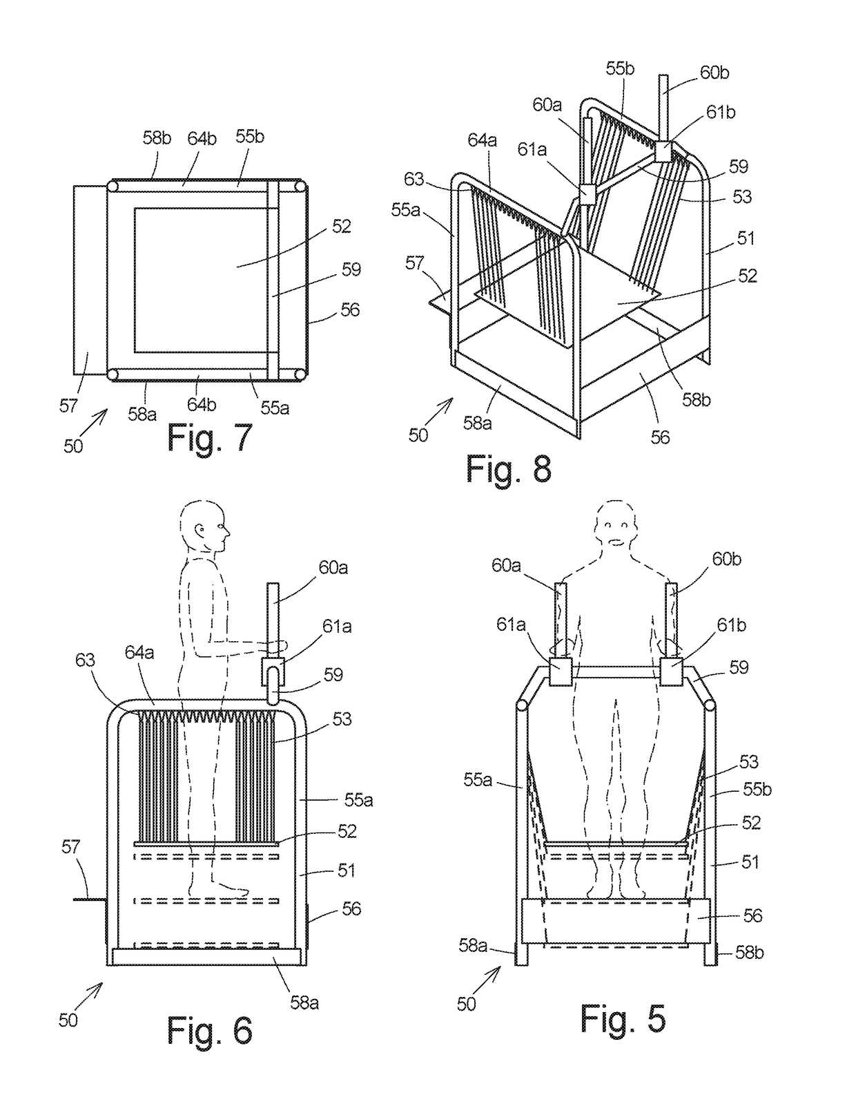
[0076]In FIGS. 4-8, a rebound training device, generally designated 50, is seen to include a frame structure, generally designated 51, a footboard 52, and a plurality of resilient elements, collectively designated 53, suspending the footboard 52 from the frame structure 51. Herein, the frame structure 51 includes a pair of spaced, inverted, U-shaped, tubular side frames 55a and 55b, a front brace plate 56, an L-shaped rear step-brace 57 extending between the side frames 55a and 55b, a pair of lower side brace plates 58a and 58b, and a tubular cross member 59. Attached to the angular cross member 59, which rises above the side frames 55a and 55b, are a pair of upright handlebars 60a and 60b secured to the round cross member 59 by clamps 61a and 61b allowing horizontal adjustment of the spacing between the handlebars 60a and 60b and the vertical angle thereof. Herein, the frame components are formed from 2-inch round tube and brace elements from flat plate. The frame structure 51, exc...

third embodiment

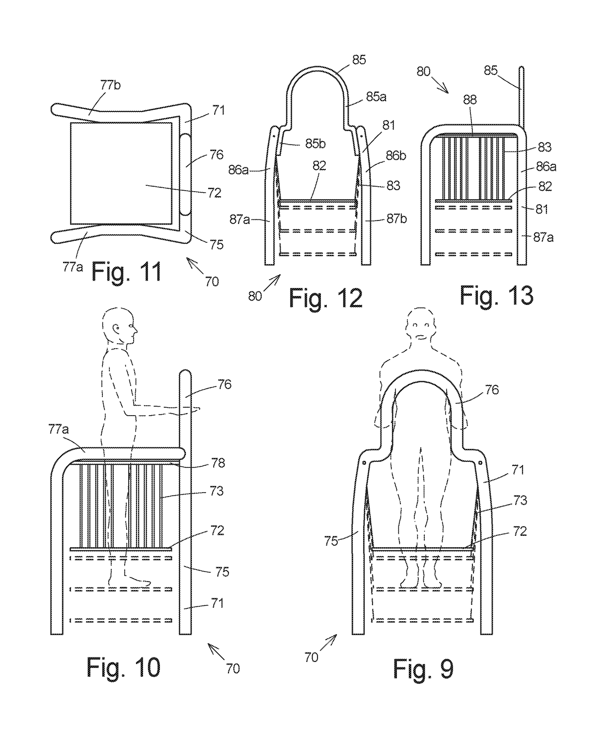
[0078]In FIGS. 9-11, a rebound training device, generally designated 70, is seen to include a frame structure, generally designated 71, a footboard 72, and a plurality of resilient elements, collectively designated 73, suspending the footboard 72 from the frame structure 71. Herein, the frame structure 71 includes an inverted, generally U-shaped, tubular front frame 75 with an upper, grippable, narrow portion 76, and a pair of spaced, inverted, L-shaped, tubular side frames 77a and 77b having their forward ends fixed to the rear surface of the front frame 75. The side frames 77a and 77b converge inwardly along their upper portions to provide gripping areas in the center thereof for the user. Herein, the frame components are formed from 2.5-inch round tube. The frame structure 71, excluding the cross member, handlebars and step, is approximately 36 inches wide, 36 inches long and 68 inches high.

[0079]Similar to the footboard shown in FIG. 3, the footboard 72 has an array of periphera...

fourth embodiment

[0080]In FIGS. 12 and 13, a rebound training device, generally designated 80, is seen to include a frame structure, generally designated 81, a footboard 82, and a plurality of resilient elements, collectively designated 83, suspending the footboard 82 from the frame structure 81. Herein, the frame structure 81 includes an inverted U-shaped, tubular front frame 85, which provides upright gripping sections 85a and lower spaced attaching sections 85b, and a pair of spaced, inverted, U-shaped, tubular side frames 86a and 86b. The front frame 85 extends between the side frames 86a and 86b and is secured on the downwardly extending forward portions 87a and 87b of the side frames 86a and 86b. The resilient elements 83 extend between horizontal hanger bar 88 and the footboard 82. Herein, the side frames 86a and 86b are formed from 3-inch round tube and the front frame 85 is formed from 1.5-inch round tube. The frame structure 81, excluding the cross member, handlebars and step, is approxima...


PUM


Abstract

A rebound and balance training device includes a frame, a footboard, a carrier for the footboard and a plurality of resilient spring elements extending between and attached to the frame and the carrier to support the footboard above a supporting surface. A user standing on the footboard manually effects repeated vertical bouncing movement between upper and lower positions. The distance traveled by the footboard, the effort required to effect movement, and the stability thereof may be modified by selectively modifying the number, the length, the position, or the elasticity of the resilient elements. In one embodiment, a pair of footboards is employed to simulate skiing movements.

Description

CROSS-REFERENCE TO RELATED APPLICATIONS[0001]This application is a continuation-in-part and claims priority from U.S. Nonprovisional application Ser. No. 15 / 495,907, filed Apr. 24, 2017, now U.S. Pat. No. 9,776,030, issued Oct. 3, 2017; U.S. Nonprovisional application Ser. No. 15 / 495,907 is a continuation-in-part and claims priority from U.S. Nonprovisional application Ser. No. 14 / 816,055, filed Aug. 2, 2015, now U.S. Pat. No. 9,630,040, issued Apr. 25, 2017; U.S. Nonprovisional application Ser. No. 14 / 816,055 is a continuation-in-part and claims priority from U.S. Nonprovisional application Ser. No. 13 / 602,087, filed Aug. 31, 2012, and U.S. Design application Ser. No. 29 / 462,670, filed Aug. 6, 2013, now U.S. Pat. No. Des. 735,819, issued Aug. 4, 2015; and, U.S. Nonprovisional application Ser. No. 13 / 602,087 claims the benefit of U.S. Provisional Application Ser. No. 61 / 530,942 filed Sep. 3, 2011.DESCRIPTIONBackground of the InventionTechnical Field[0002]The present invention pertai...

Claims


Application Information

Patent Timeline
Patent Type & Authority Patents(United States)
IPC IPC(8): A63B26/00A63B21/00
CPCA63B26/003A63B21/4035A63B71/0619A61H1/005A61H23/00A63B1/00A63B5/11A63B17/00A63B21/023A63B21/0442A63B21/0552A63B21/068A63B22/18A63B23/0211A63B23/03525A63B23/03533A63B23/0405A63B23/1218A63B23/1227A61H2201/0192A61H2201/1261A61H2201/1284A61H2201/1635A61H2201/1666A61H2201/1671A61H2201/5043A61H2203/0406A63B2023/003A63B2023/0411A63B2071/0063A63B2071/0694A63B2209/02A63B2225/09A63B2225/093A63B21/00065A63B21/4034A63B21/4049A63B69/0062
Inventor LOUIS, JOHN G
Owner LOUIS JOHN G
Why Eureka
Try Eureka