Rotation speed measuring system

a technology of rotating speed and measuring system, which is applied in the direction of acceleration measurement in multiple dimensions, acceleration measurement using interia forces, instruments, etc., can solve the problems of difficult to detect the time point at which the midair movement of the ball ends, and the speed measuring system in some cases cannot automatically detect a time point, etc., to achieve the effect of short time, affecting accurate determination, and greatly changing the acceleration of the ball

Active Publication Date: 2019-01-22
AICHI STEEL
View PDF7 Cites 1 Cited by
  • Summary
  • Abstract
  • Description
  • Claims
  • Application Information

AI Technical Summary

Benefits of technology

[0009]The present invention has been made in such circumstances, providing a rotation speed measuring system that enables automatic detection of a time point at which the midair movement of a ball ends.
[0016]Thus, the end detecting unit enables the detection of the end time point at which the midair movement of the ball can be considered to end. That is, while moving in midair, the ball receives substantially no large external forces except little air resistance. Thus, during the midair movement of the ball, the acceleration sensor hardly detects accelerations caused by external forces, but mainly detects an acceleration caused by a centrifugal force generated by the rotation of the ball. The detected acceleration is substantially constant. Therefore, during this state, the output of the acceleration sensor is substantially constant. At the moment when the ball hits an external object such as a mitt to end the midair movement, the ball receives a great force, and the acceleration of the ball changes greatly in a short time. Thus, making use of changes in acceleration detectable with the acceleration sensor enables to detect the end time point. That is, it is possible to detect, as the end time point, a time point of a switch from a state in which the acceleration does not change greatly for a certain amount of time (the small-variation state) during the time when the ball moves in midair, to a state in which the acceleration changes greatly in a short time (the large-variation state).
[0017]It is noted that an acceleration sensor without offset correction does not output zero when an actual acceleration is zero. In addition, if an acceleration sensor cannot be fixed in the center of a ball, the acceleration sensor will receive an acceleration caused by a centrifugal force at high rotation speeds of the ball. Therefore, when detected values from the acceleration sensor, as such, is used to determine the time point of a switch from the small-variation state to the large-variation state, it is difficult to set a threshold value, which may hinder accurate determination. Thus, the present embodiment is configured to determine the time point of the switch from the small-variation state to the large-variation state by making use of the acceleration variation. Making use of the acceleration variation enables accurate and easy determination of the time point of the switch from the small-variation state to the large-variation state.
[0018]As described above, according to the present invention, it is possible to provide a rotation speed measuring system that enables automatic detection of a time point at which the midair movement of a ball ends.

Problems solved by technology

However, the rotation speed measuring system in some cases cannot automatically detect a time point at which midair movement of the ball ends.
Therefore, it is difficult to detect the time point at which the midair movement of the ball ends.

Method used


Image

  • Rotation speed measuring system
  • Rotation speed measuring system
  • Rotation speed measuring system

Examples


embodiments

(Embodiment 1)

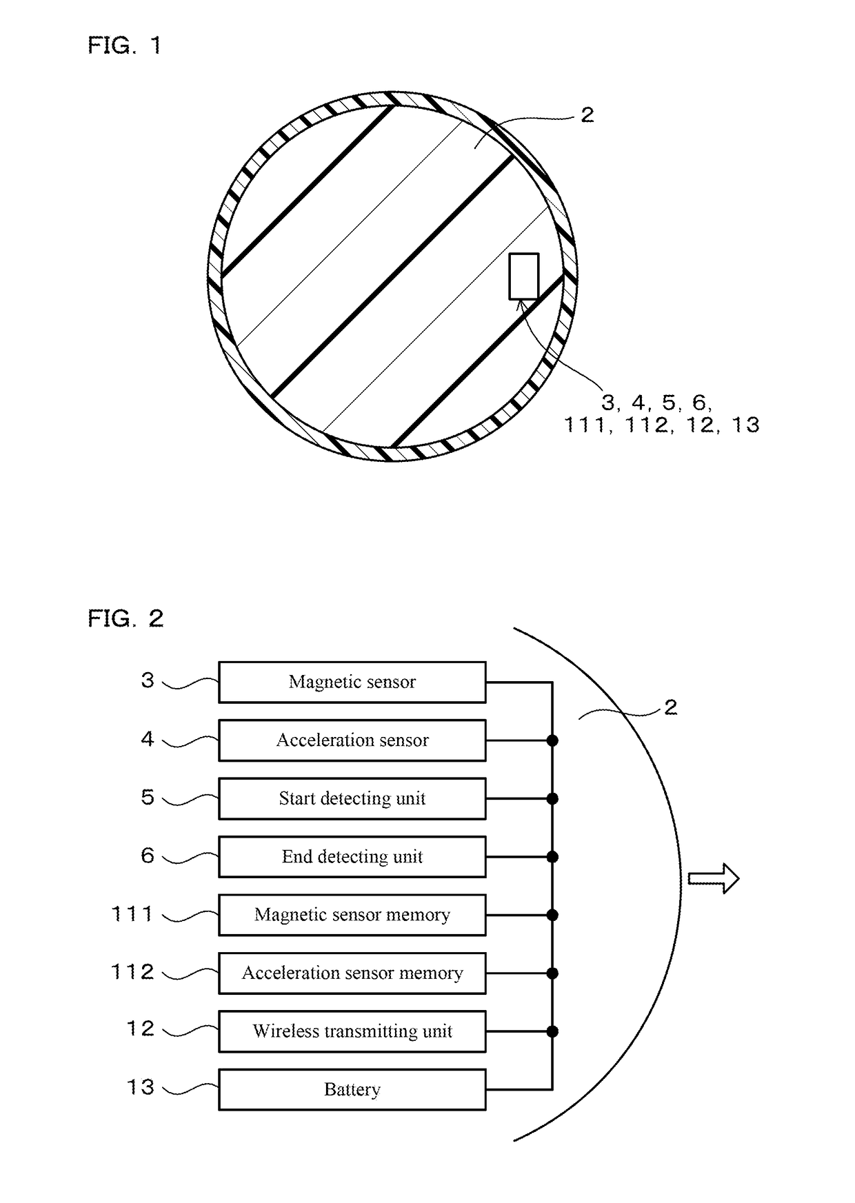
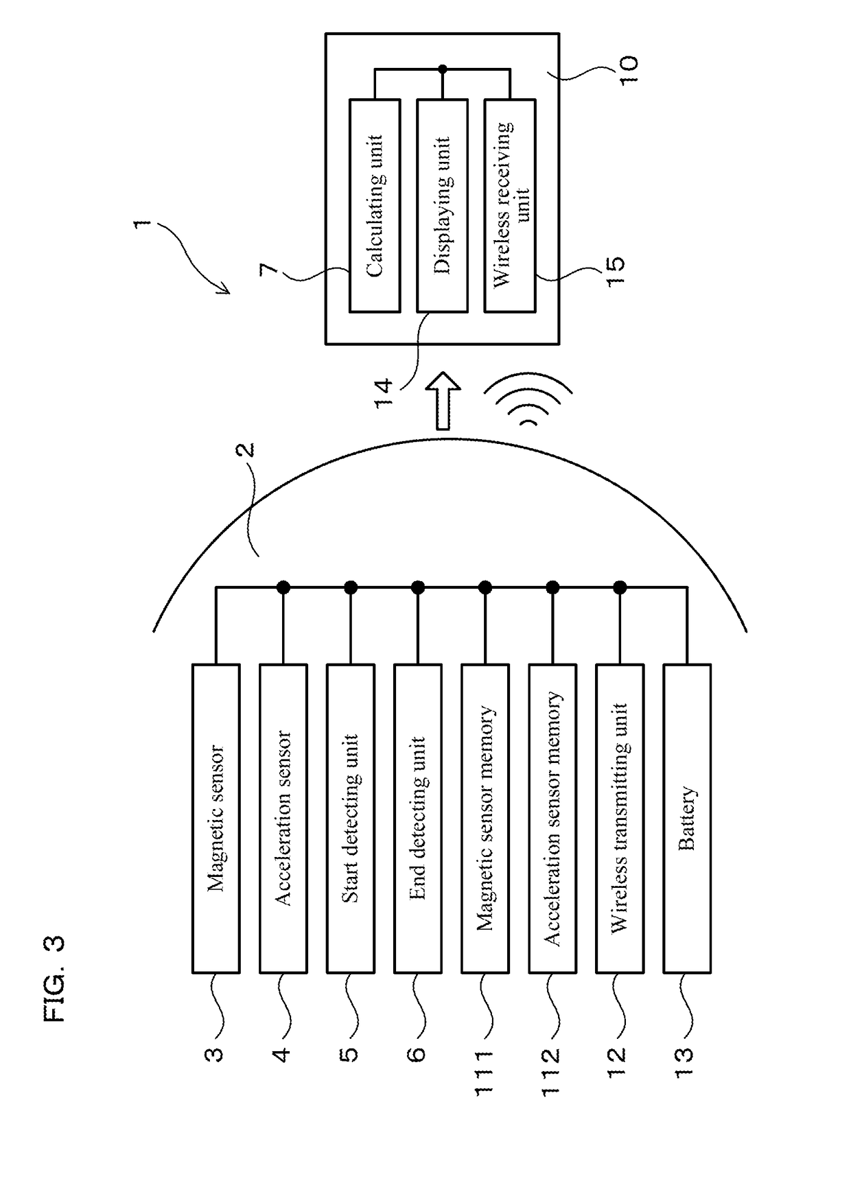
[0051]An embodiment of the aforesaid rotation speed measuring system will be described with reference to FIG. 1 to FIG. 8. A rotation speed measuring system 1 in the present embodiment includes, as illustrated in FIG. 1 to FIG. 3, a magnetic sensor 3, an acceleration sensor 4, an end detecting unit 6, and a calculating unit 7. The magnetic sensor 3 measures earth magnetism in at least one axis direction. The acceleration sensor 4 measures acceleration in at least one axis direction. The magnetic sensor 3 and the acceleration sensor 4 are provided in a ball 2.

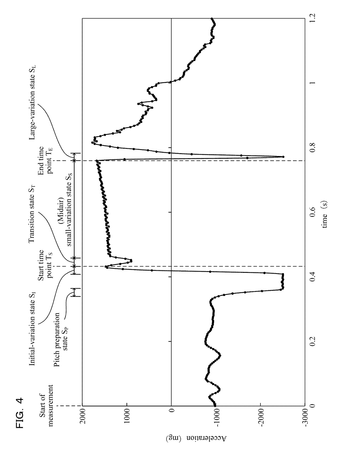
[0052]The end detecting unit 6 detects, as an end time point TE at which midair movement of the ball 2 is considered to end, a time point of a switch at which an acceleration variation |ΔA| obtained as an absolute value of a variation in the acceleration measured by the acceleration sensor in a predetermined small time unit (see FIG. 5) is switched to a large-variation state SL after a small-variation state SS (see...

embodiment 2

(Embodiment 2)

[0105]In the following embodiments, among reference numerals used in the drawings, reference numerals identical to those used in Embodiment 1 refer to identical elements or the like in Embodiment 1, unless otherwise noted.

[0106]The present embodiment is an example in which a different method is used to transmit measurement data on the earth magnetism. As illustrated in FIG. 9, in the present embodiment, a connector 16 is formed in the ball 2. As in Embodiment 1, the ball 2 is configured to store measurement data on the earth magnetism in the magnetic sensor memory 111 while moving in midair. Then, after the midair movement of the ball 2 ends, as illustrated in FIG. 10, a line 17 is connected to the connector 16, and the measurement data on the earth magnetism stored in the magnetic sensor memory 111 is transmitted to the external device 10 through this line 17.

[0107]Besides, the present embodiment has the configuration and the operational advantages similar to Embodime...

embodiment 3

(Embodiment 3)

[0108]The present embodiment is an example in which the configuration of components in the ball 2 is changed. As illustrated in FIG. 11, in the present embodiment, the ball 2 is equipped therein with all the components constituting the rotation speed measuring system 1. That is, the ball 2 is provided therein with the magnetic sensor 3, the acceleration sensor 4, the start detecting unit 5, the end detecting unit 6, the magnetic sensor memory 111, the battery 13, the calculating unit 7, and the displaying unit 14. As in Embodiment 1, in the present embodiment, the start detecting unit 5 and the end detecting unit 6 are used to detect the start time point TS and the end time point TE. The calculating unit 7 calculates the rotation speed of the ball 2 moving in midair by making use of the measurement data on the earth magnetism acquired from the start time point TS until the end time point TE by the magnetic sensor 3. Then, the calculated rotation speed is displayed on t...


PUM


Abstract

A rotation speed measuring system includes a magnetic sensor, an acceleration sensor, an end detecting unit, and a calculating unit. The magnetic sensor measures earth magnetism in at least one axis direction. The acceleration sensor measures acceleration in at least one axis direction. The end detecting unit detects a time point of a switch at which an acceleration variation is switched to a large-variation state after a small-variation state, wherein the small-variation state corresponds to a state in which the acceleration variation is equal to or below a predetermined first threshold value and the large-variation state corresponds to a state in which the acceleration variation is equal to or above a predetermined second threshold value. The calculating unit calculates the rotation speed of the ball moving in midair by analyzing a frequency of measurement data on the earth magnetism acquired by the magnetic sensor until the end time point.

Description

CROSS-REFERENCE TO RELATED APPLICATION[0001]The present application claims priority under 35 U.S.C. § 119 to Japanese Application No. 2015-144295, filed on Jul. 21, 2015, entitled “ROTATION SPEED MEASURING SYSTEM”. The contents of this application are incorporated herein by reference in their entirety.BACKGROUND OF THE INVENTION[0002]Field of the Invention[0003]The present invention relates to a rotation speed measuring system for measuring the rotation speed of a ball moving in midair.[0004]Description of the Related Art[0005]As a rotation speed measuring system for measuring the rotation speed of a ball moving in midair, a rotation speed measuring system is known that includes a magnetic sensor that measures earth magnetism (see Patent Literature 1 described below). In the rotation speed measuring system, the magnetic sensor is provided in a ball, and temporal changes in output of the magnetic sensor are used to calculate the rotation speed of the ball moving in midair.[0006]When ...

Claims


Application Information

Patent Timeline
Patent Type & Authority Patents(United States)
IPC IPC(8): G01P3/48G01P3/487G01R33/06G01P15/18
CPCG01R33/063G01P3/487G01P15/18
Inventor URAKAWA, KAZUOYAMAMOTO, MICHIHARU
Owner AICHI STEEL
Why Eureka
Try Eureka