
Brake for bicycle

a technology for brakes and bicycles, applied in the direction of cycle brakes, cycle equipment, etc., can solve the problems of prolonged brake reaction time and poor brake effect, and achieve the effect of reducing brake reaction time and effective brak

Active Publication Date: 2019-01-29
WEN YUAN HUNG
View PDF29 Cites 1 Cited by
  • Summary
  • Abstract
  • Description
  • Claims
  • Application Information

AI Technical Summary

Benefits of technology

The solution reduces brake reaction time, evenly distributes force across both braking members, and prevents excessive wear, thereby enhancing the braking effectiveness and safety of the bicycle.

Problems solved by technology

However, in this type of prior art, the two arm assemblies of the brake cannot swing synchronously to clip the wheel rim; that is, two brake sides of the wheel rim are not applied with brake at the same time, so the two brake sides receive forces in different intensities.
As a result, the brake reaction time is prolonged, and each braking member will be abraded on single side, and the braking effect is poor.

Method used


Image

  • Brake for bicycle
  • Brake for bicycle
  • Brake for bicycle

Examples


Embodiment Construction

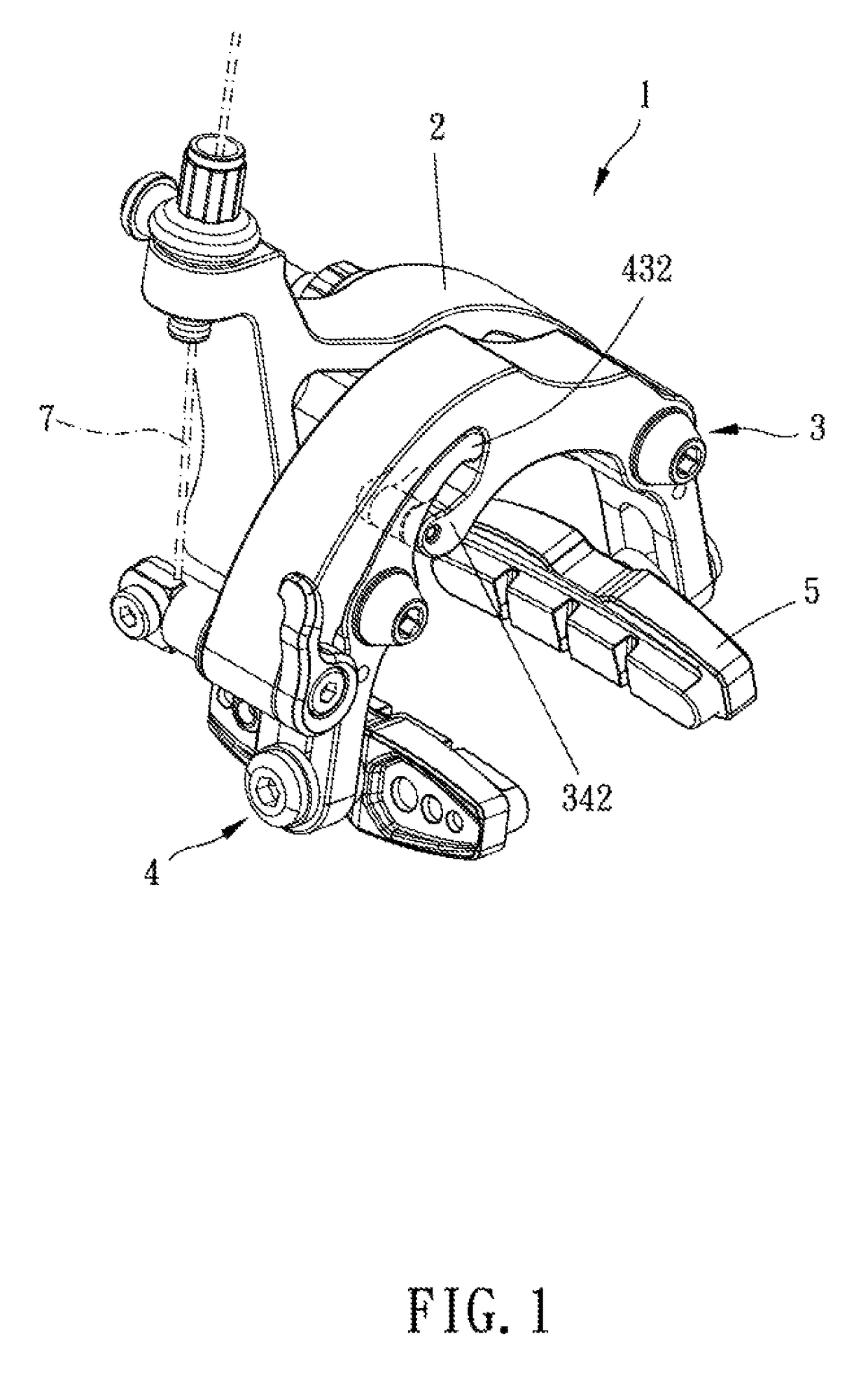
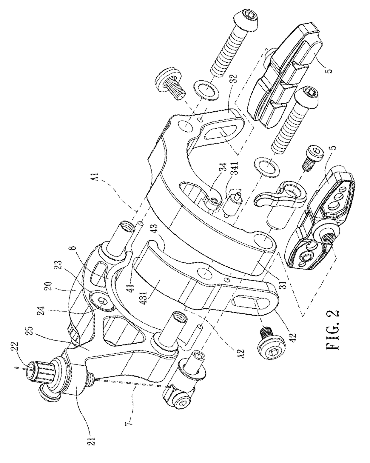
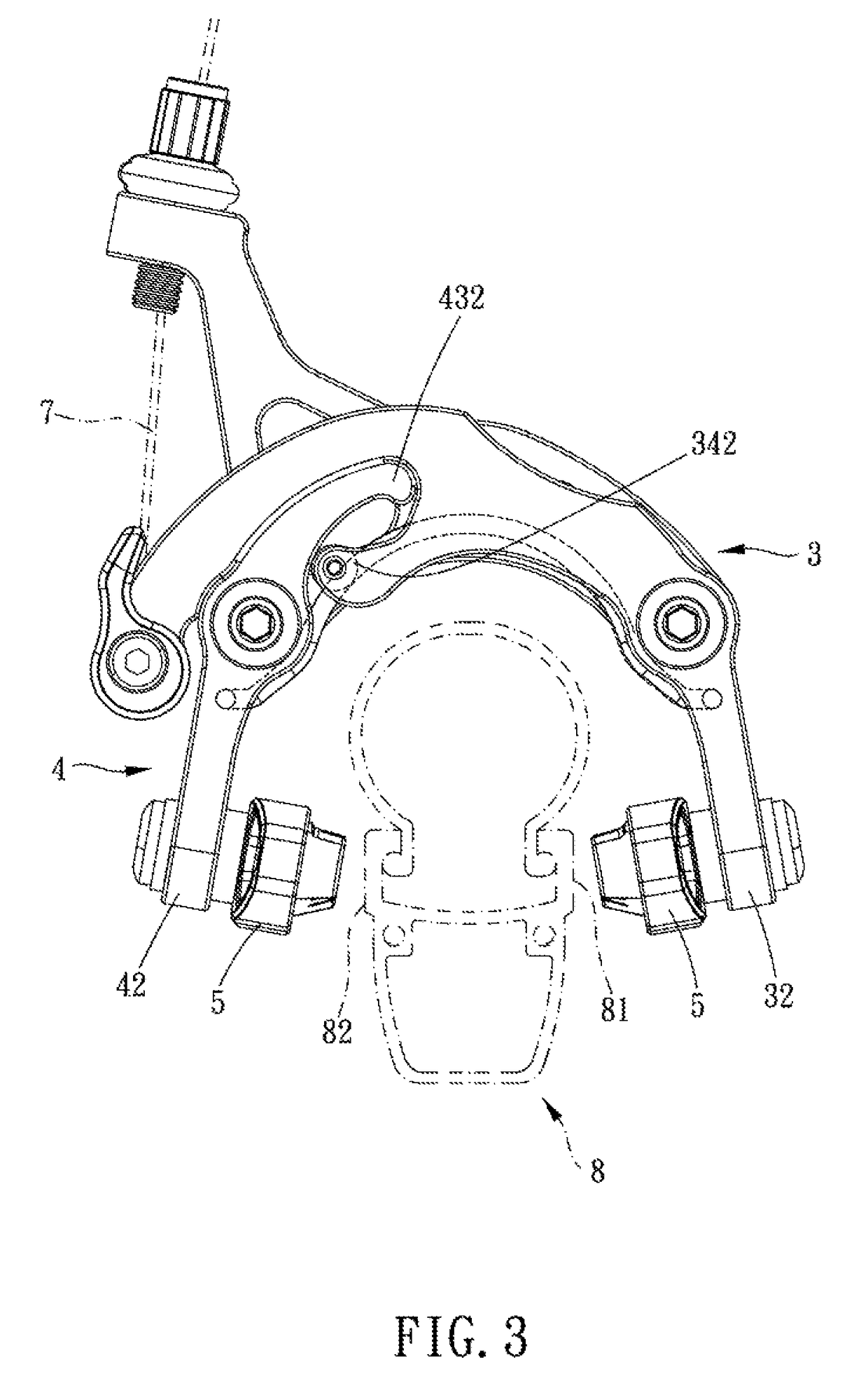
[0013]Please refer to FIGS. 1 to 4 for a preferred embodiment of the present invention. A brake 1 for a bicycle includes a base 2, a first arm assembly 3 and a second arm assembly 4.

[0014]The base 2 is for being fixedly connected to a frame (not shown) of a bicycle. The first arm assembly 3 is pivoted to the base 2, the first arm assembly 3 has a first end portion 31, a second end portion 32 and a first abutting portion 34, the first end portion 31 is for connection of a brake line 7, and the second end portion 32 is swingable toward a first brake side 81 of a wheel rim 8 to frictionally contact the first brake side 81. The second arm assembly 4 is pivoted to the base 2 and corresponds to the first arm assembly 3, and the second arm assembly 4 has a third end portion 41, a fourth end portion 42 and a second abutting portion 43 arranged on the third end portion 41. The second abutting portion 43 is located correspondingly above the first abutting portion 34 and interferable with the ...


PUM


Abstract

A brake for a bicycle includes a base, first and second arm assemblies. The first and second arm assemblies are pivoted to the base. The first arm assembly has a first end portion, for connection of a brake line a second end portion for frictionally contacting a brake side of a wheel rim. The second arm assembly is pivoted to the base and corresponds to the first arm assembly. The second arm assembly has a third end portion, a fourth end portion and a second abutting portion which is arranged on the third end portion. The second abutting portion is located correspondingly above the first abutting portion and interferable with the first abutting portion in a pivoting direction of the first abutting portion. The fourth end portion is swingable toward the brake side to clip the other brake side of the wheel rim.

Description

[0001]This application is a Continuation-in-Part of application Ser. No. 14 / 992,293, filed on Jan. 11, 2016, for which priority is claimed under 35 U.S.C. § 120; and this application claims priority of Application No. 104109391 filed in Taiwan on Mar. 24, 2015 under 35 U.S.C. § 119, the entire contents of all of which are hereby incorporated by reference.BACKGROUND OF THE INVENTIONField of the InventionDescription of the Prior Art[0002]Recently, riding a bicycle has become a fad, and bicycle racings are often held; therefore, how to allow a cyclist to ride a bicycle faster is one of the features that the bicycle manufacturers want to improve. In addition, another feature to be improved is a brake system of the bicycle because the brake system has a direct influence on the safety of the cyclist. Conventionally, a brake for a bicycle has two arm assemblies corresponding to each other. One of the arm assemblies is driven by a brake line to swing toward a brake side of a wheel rim, and ...

Claims


Application Information

Patent Timeline
Patent Type & Authority Patents(United States)
IPC IPC(8): B62L3/00B62L1/16
CPCB62L1/16
Inventor WEN, YUAN-HUNG
Owner WEN YUAN HUNG
Learn More