Engine braking device
An engine braking and driving force technology, applied in engine components, machines/engines, valve devices, etc., can solve the problems of large inertia of the braking system, increased engine height and manufacturing cost, slow response, etc., to reduce costs and reduce costs. Small size and weight, the effect of reducing requirements
- Summary
- Abstract
- Description
- Claims
- Application Information
AI Technical Summary
Problems solved by technology
Method used
Image
Examples
Embodiment 1
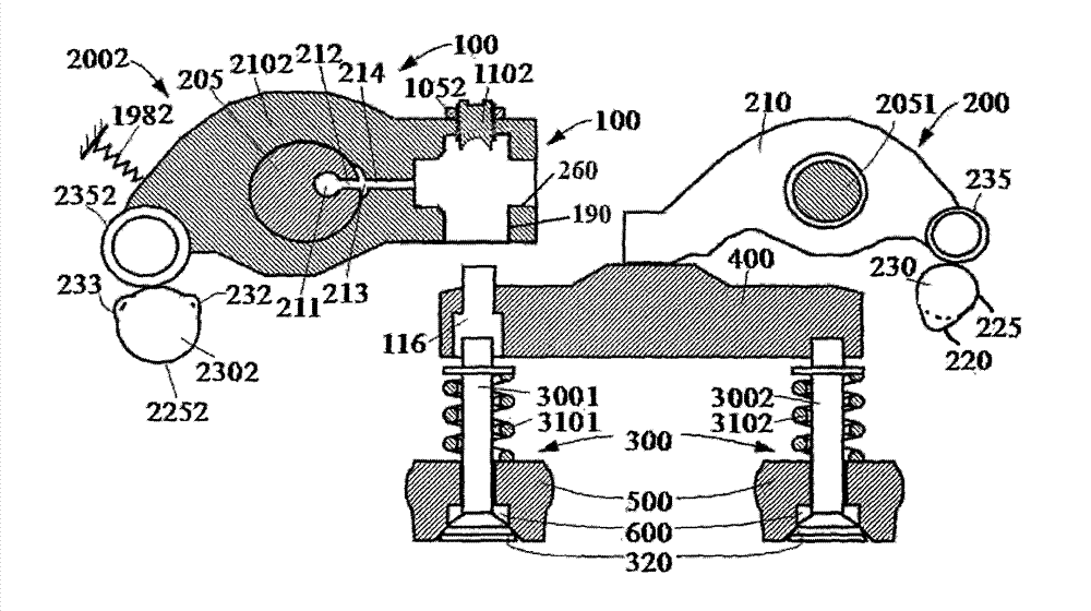
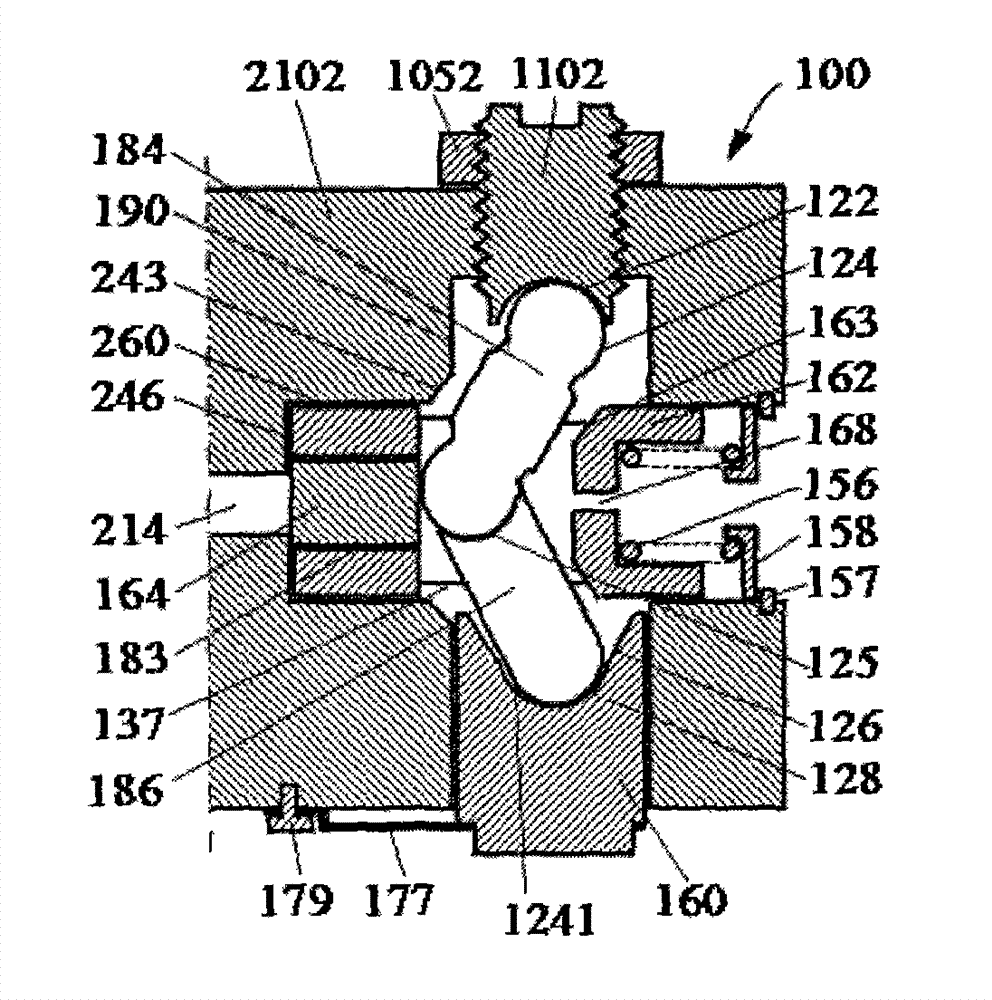
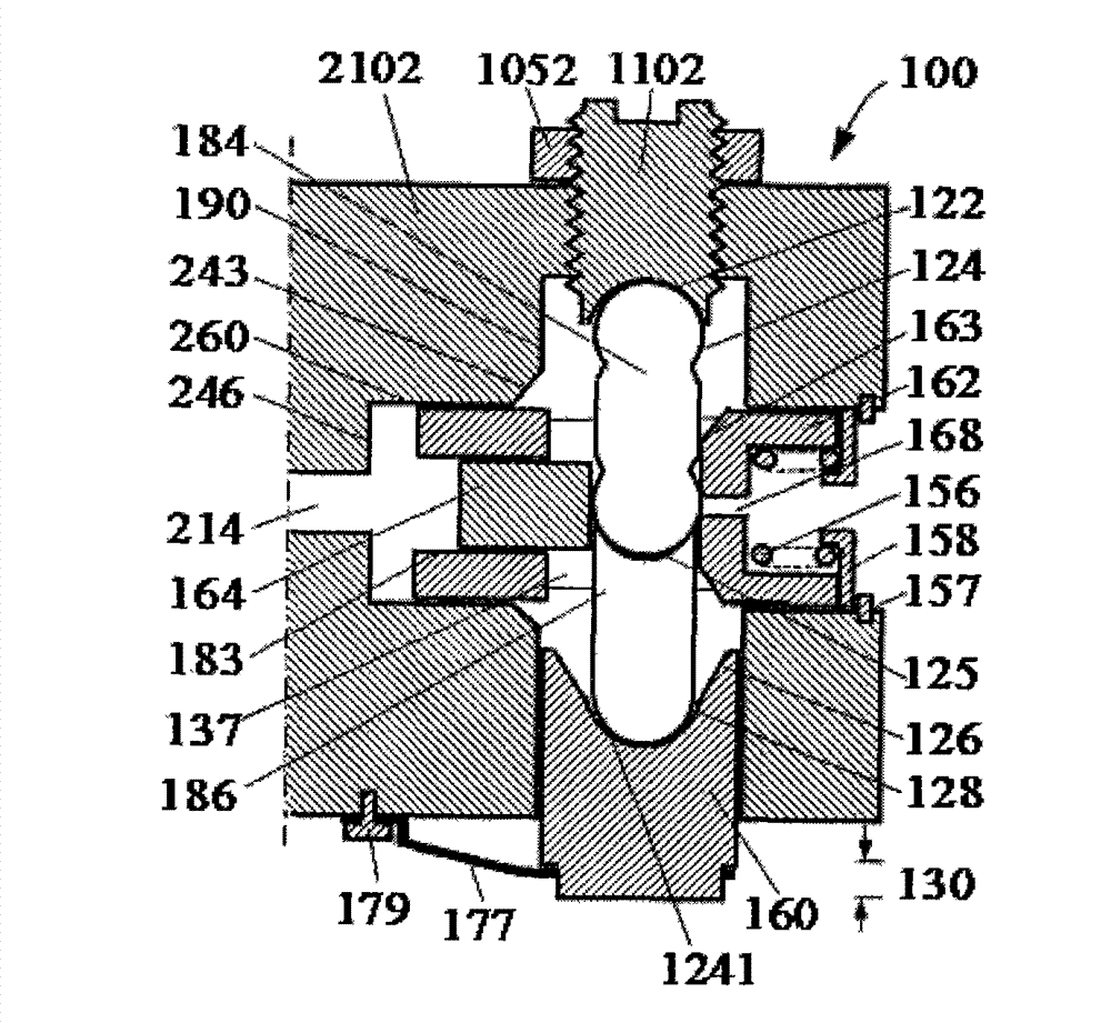
[0025] Such as figure 1 , figure 2 , image 3 , Figure 4 and Figure 5As shown, an engine braking device 100 of the present invention is composed of an exhaust valve control mechanism 200, wherein the exhaust valve control mechanism 2002 is composed of a driving force input cam 2302, a cam follower 2352, a rocker arm 2102 Constituted with the rocker shaft 205, the middle part of the rocker arm 2102 is arranged on the rocker shaft 205, the driving force input cam 2302 is arranged outside the cam follower 2352, and the rotation of the protrusion in the driving force input cam 2302 The circumference intersects the outer circumference of the cam follower 2352, a bias return spring 1982 is provided on the outside of the rocker arm 2102, a fluid passage 214 is arranged in the rocker arm 2102, and a fluid passage 211 is arranged axially in the rocker arm shaft 205 1. A radial hole 212 is arranged along a radius, and the radial hole 212 communicates with the fluid channel 211. A...
PUM
 Abstract
Description
Claims
Application Information
 - R&D
- Intellectual Property
- Life Sciences
- Materials
- Tech Scout
- Unparalleled Data Quality
- Higher Quality Content
- 60% Fewer Hallucinations
Browse by: Latest US Patents, China's latest patents, Technical Efficacy Thesaurus, Application Domain, Technology Topic, Popular Technical Reports.
© 2025 PatSnap. All rights reserved.Legal|Privacy policy|Modern Slavery Act Transparency Statement|Sitemap|About US| Contact US: help@patsnap.com


