Improved engine brake driving device
A technology of engine braking and driving devices, which is applied in the direction of engine components, machines/engines, valve devices, etc., can solve the problems of slow response, large inertia of the braking system, increased engine height and manufacturing costs, etc., to achieve reduction requirements, Effects of cost reduction, volume and weight reduction
- Summary
- Abstract
- Description
- Claims
- Application Information
AI Technical Summary
Problems solved by technology
Method used
Image
Examples
Embodiment 1
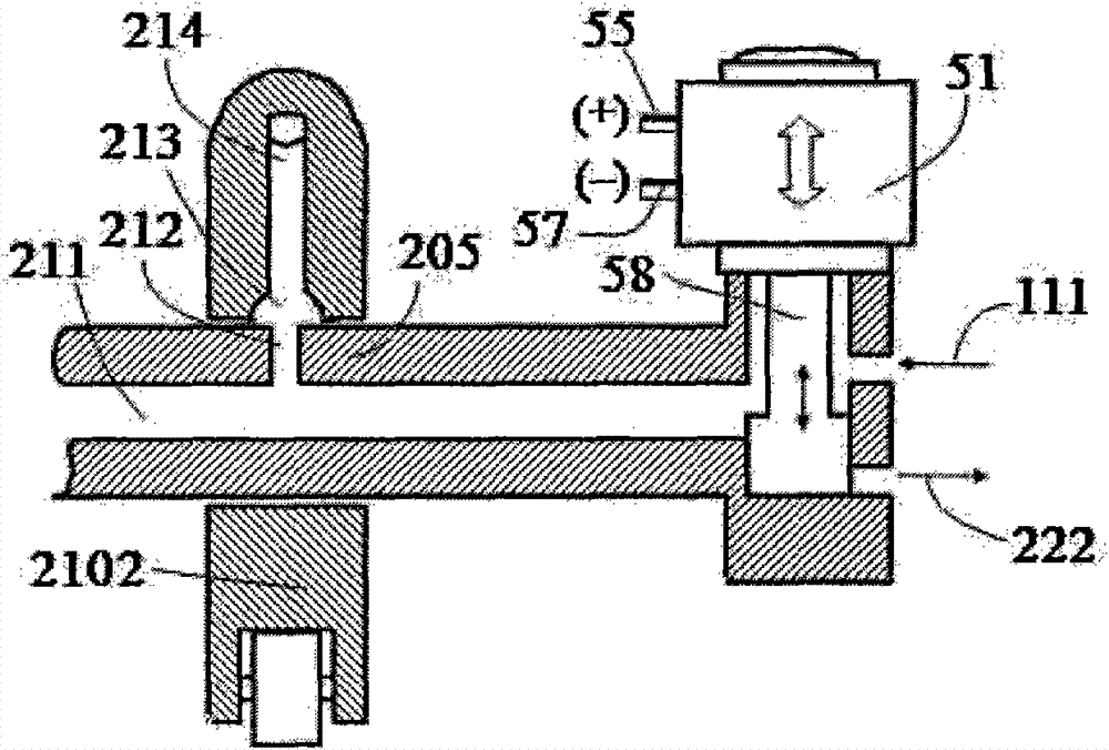
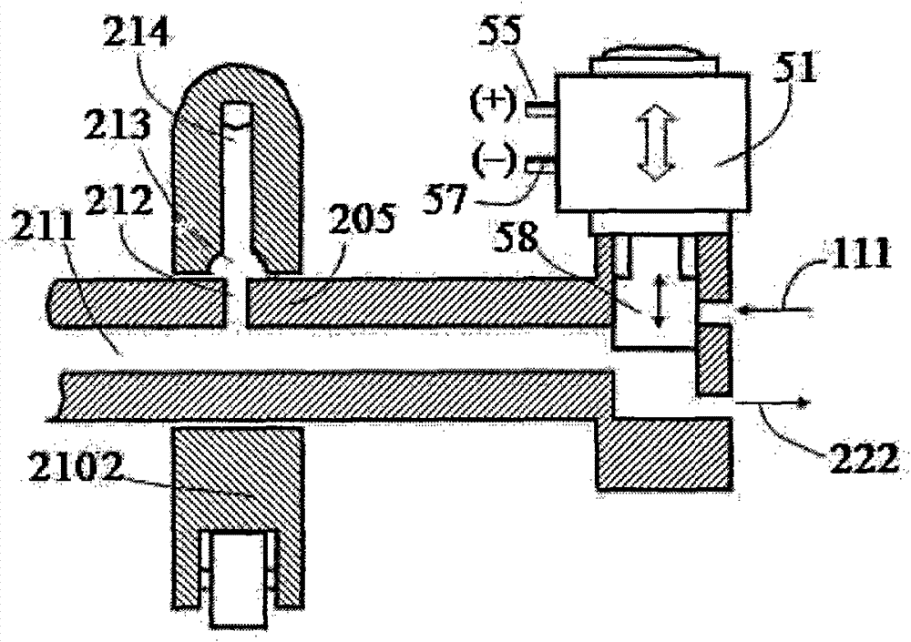
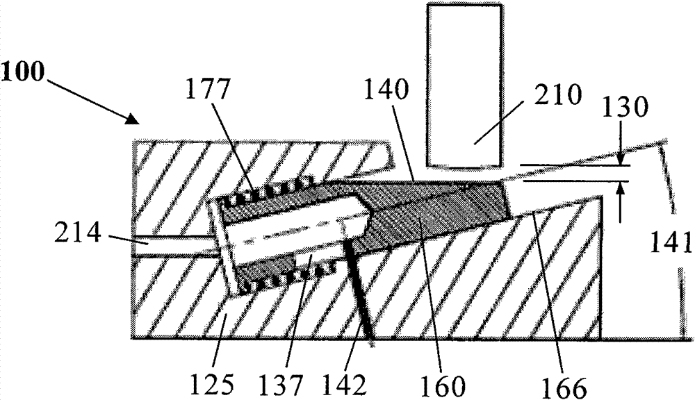
[0030] Such as figure 1 , figure 2 , image 3 with Figure 4 As shown, an improved engine brake driving device 100 of the present invention is composed of an exhaust valve control mechanism, wherein the exhaust valve control mechanism is composed of a brake box 125, a brake plunger 160 and a brake The movable connector 210 is composed of a plunger hole 166 in the brake box 125, and the brake plunger 160 is provided in the plunger hole 166 in a sliding manner. A liquid seal is provided with the plunger hole 166, the brake plunger 160 has a working surface 140, and the working surface 140 forms an included angle 141 with the center axis of the brake plunger 160, A fluid channel 214 is provided in the brake box 125 to communicate with the plunger hole 166.
[0031] Further, a brake plunger stroke control mechanism is provided between the brake plunger 160 and the brake box 125, and the brake plunger stroke control mechanism consists of a spring 177 and a positioning pin 142 The sp...
Embodiment 2
[0042] Such as Figure 5 with Image 6 As shown, the structure of this embodiment is approximately the same as that of the first embodiment, except that the brake connecting member 210 is arranged under the brake piston 160.
Embodiment 3
[0044] Such as Figure 7 As shown, the difference between this embodiment and Embodiment 1 is that the brake plunger 160 is horizontally arranged in the plunger hole 166 of the exhaust valve bridge 125.
[0045] Further, a screw 175 is provided between the end of the brake plunger 160 where the spring 177 is provided and the exhaust valve bridge 125, and the screw 175 is fixed to the exhaust valve through a nut 173. The gas valve is on the valve bridge 125. The stroke 136 of the plunger 160 is controlled by adjusting the distance between the end surface of the screw 175 and the spring seat 176 fixed on the plunger 160. After the distance is adjusted, the screw 175 is fixed on the valve bridge 215 by the nut 173. The screw 175 is not only used to control the stroke 136 of the brake plunger 160, but also serves as a spring seat for the brake spring 177. The other end of the spring 177 is fixed on the spring seat 176, and the spring seat 176 is fixed on the brake plunger 160. Ends...
PUM
 Abstract
Description
Claims
Application Information
 - R&D
- Intellectual Property
- Life Sciences
- Materials
- Tech Scout
- Unparalleled Data Quality
- Higher Quality Content
- 60% Fewer Hallucinations
Browse by: Latest US Patents, China's latest patents, Technical Efficacy Thesaurus, Application Domain, Technology Topic, Popular Technical Reports.
© 2025 PatSnap. All rights reserved.Legal|Privacy policy|Modern Slavery Act Transparency Statement|Sitemap|About US| Contact US: help@patsnap.com


