Image display device and method for dimming light source

a technology of image display device and light source, which is applied in the direction of static indicating device, instruments, etc., can solve the problems of unnatural brightness of displayed image, difficulty in displaying images having different characteristics at the optimum brightness, and the process of detecting image characteristics to distinguish the first and second images described above becomes increasingly complex

Active Publication Date: 2019-01-29
SHARP NEC DISPLAY SOLUTIONS LTD
View PDF17 Cites 0 Cited by
  • Summary
  • Abstract
  • Description
  • Claims
  • Application Information

AI Technical Summary

Benefits of technology

[0013]If a detailed histogram of 16 levels is used in place of a three-level histogram, the image characteristics quantity can be detected more precisely, and the light quantity of the backlight can therefore be precisely adjusted. In this case, however, the process of detecting the image characteristics to distinguish the first and second images described above becomes increasingly complex as the levels of brightness become more detailed.
[0014]It is an object of the present invention to provide an image display device and light source dimming method that can provide an image that has natural brightness by dimming control and thus solve the above-described problem.

Problems solved by technology

As described hereinabove, the control method disclosed in Patent Document 1 has the problem of the difficulty of displaying images having different characteristics at the optimum brightness.
As a result, the brightness of the displayed image will be unnatural in some cases.
In this case, however, the process of detecting the image characteristics to distinguish the first and second images described above becomes increasingly complex as the levels of brightness become more detailed.

Method used


Image

  • Image display device and method for dimming light source
  • Image display device and method for dimming light source
  • Image display device and method for dimming light source

Examples


first exemplary embodiment

(First Exemplary Embodiment)

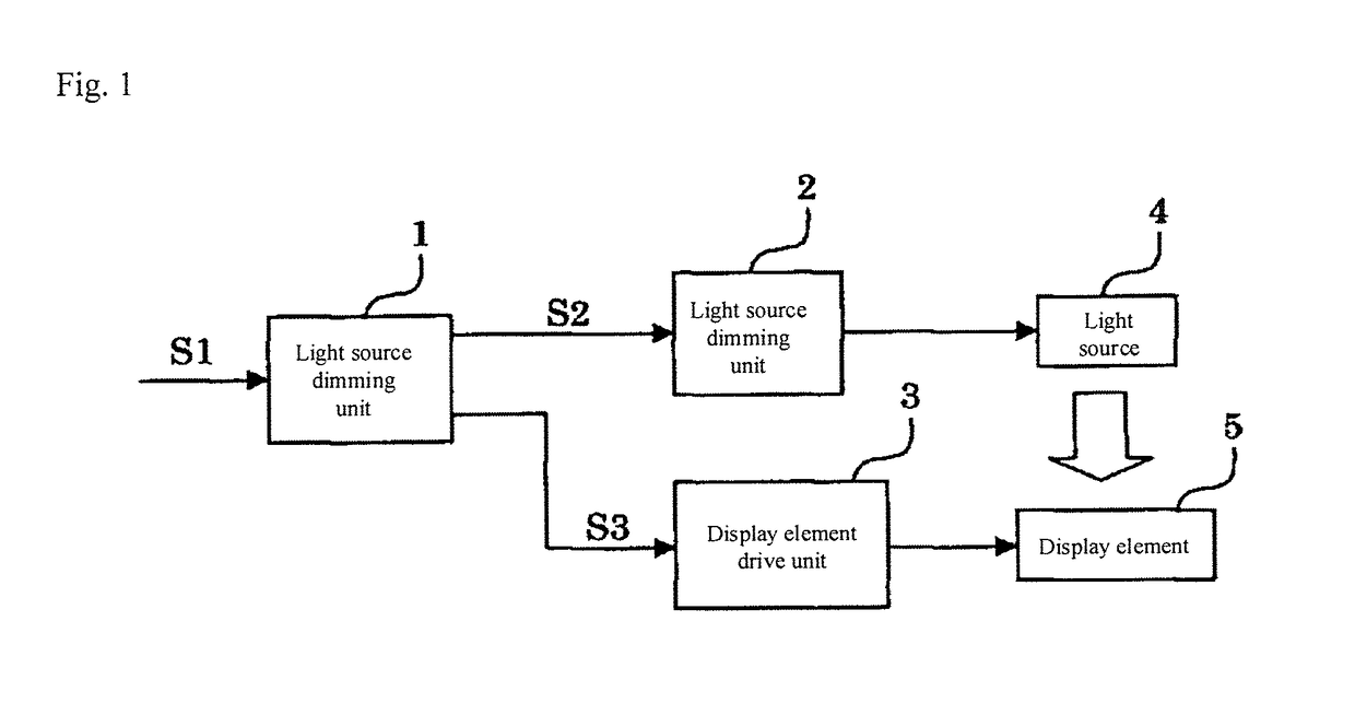
[0034]FIG. 1 is a block diagram showing the principal configuration of an image display device according to the first exemplary embodiment of the present invention.

[0035]Referring to FIG. 1, the image display device includes light source dimming unit 1, light source drive unit 2, display element drive unit 3, light source 4, and display element 5. Light source 4 is a mercury lamp or a solid-state light source such as an LED (light-emitting diode). Display element 5 is a display element that spatially modulates the light from light source 4 to form an image, and for example, is a component such as a liquid crystal display device.

[0036]Light source dimming unit 1 receives RGB signal S1 from an outside video supply device, supplies dimming signal S2 for controlling the luminance (or light quantity) of light source 4 to light source drive unit 2, and supplies RGB signal S3 for displaying images on display element 5 to display element drive unit 3. The outside...

second exemplary embodiment

(Second Exemplary Embodiment)

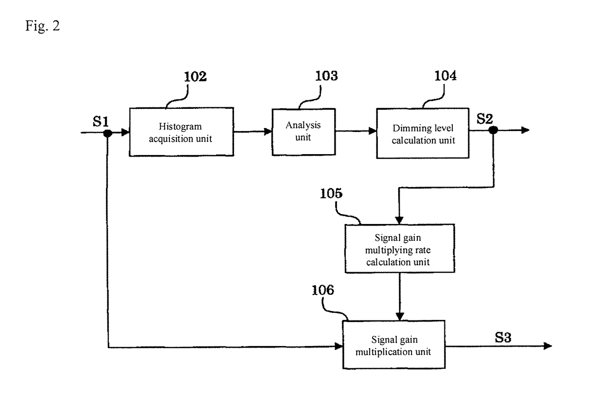
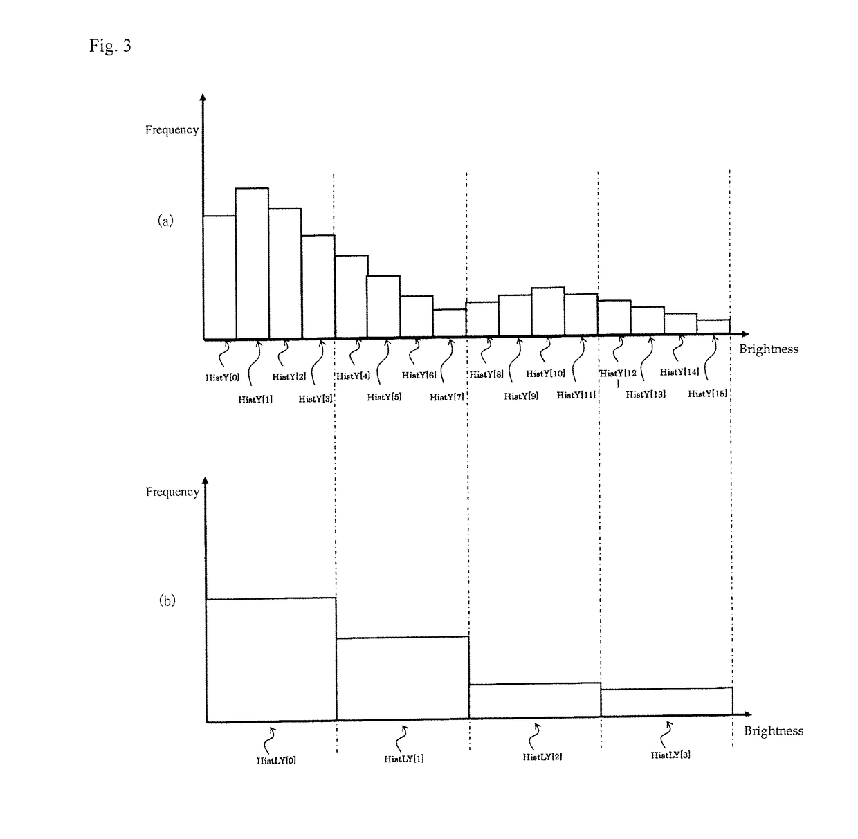
[0109]The image display device according to the second exemplary embodiment of the present invention also includes the configuration shown in FIG. 1 and FIG. 2, but the second exemplary embodiment differs from the first exemplary embodiment in that dimming control is implemented using an eight-level histogram and a four-level histogram. In the following explanation, explanation will focus on the configuration that differs from that of the first exemplary embodiment, and explanation of identical configurations will be omitted.

[0110]Histogram acquisition unit 102 calculates luminance signal Y from RGB signal S1 in accordance with the previously described Formula 1 and acquires an eight-level histogram and a four-level histogram for each of luminance signal Y, red signal R, green signal G, and blue signal B. The acquisition of these histograms is carried out in one-frame units.

[0111]The procedure of acquiring an eight-level histogram when RGB signal S1 is e...


PUM


Abstract

An image display device and a light source dimming method are provided for enabling display of an image with natural brightness through dimming control. The image display device includes: a light source; a display unit that spatially modulates light from the light source on the basis of an input video e signal to form an image; a histogram acquisition unit that, on the basis of the input video signal, acquires a first histogram, in which image data is indicated by the frequencies of levels of brightness, and a second histogram having a number of levels of brightness that differs from the number of levels of brightness of the first histogram; and a control unit that performs dimming control that adjusts the luminance of the light source on the basis of the first and second histograms.

Description

TECHNICAL FIELD[0001]The present invention relates to an image display device in which dimming control of the light source is performed and to a method for dimming a light source.BACKGROUND ART[0002]As a light source dimming method in, for example, a liquid crystal display device, a method is described in Patent Document 1 in which an average luminance value is calculated from a video signal that is acquired during a fixed time interval and the luminance of the backlight is then controlled on the basis of the average luminance value. In this control method, the luminance of the backlight is decreased when the average luminance value surpasses a threshold value, and the luminance of the backlight is increased when the average luminance value falls below a threshold value. In this way, the brightness of the screen can be adjusted to the optimum brightness according to the luminance level of the video.[0003]In the above-described control method, however, because the luminance of the ba...

Claims


Application Information

Patent Timeline
Patent Type & Authority Patents(United States)
IPC IPC(8): G09G3/00G09G3/20G09G3/36G09G3/34
CPCG09G3/36G09G3/2003G09G3/3406G09G2360/16G09G2320/06G09G2320/062G09G2320/0626G09G2320/0238
Inventor MORIMOTO, TAKESHI
Owner SHARP NEC DISPLAY SOLUTIONS LTD
Why Eureka
Try Eureka