Hand dryer

a hand dryer and hand technology, applied in the field of hand dryers, can solve the problems of product design and development, mold replacement, product design and development cost, and prolong the product development period, and achieve the effect of low production cost and flexible replacemen

Inactive Publication Date: 2019-02-05
ZHEJIANG AIKE APPLIANCE
View PDF26 Cites 1 Cited by
  • Summary
  • Abstract
  • Description
  • Claims
  • Application Information

AI Technical Summary

Benefits of technology

[0008]To solve the problem that a housing of an existing hand dryer is hard to replace, the present invention provides a hand dryer, the production cost of the hand dryer is low, and the housing of the hand dryer can be flexibly replaced.
[0023]In conclusion, compared with the prior art, the hand dryer in the invention has following advantages.
[0024]The housing of the hand dryer in the invention is designed into a hollow tube structure with two ends opened. The housing of the hand dryer can be made of stainless steel plates with different surface appearances in a direct punching manner or made of an aluminum alloy material in an extrusion manner. The formation process is simple, the material utilization rate is high, and meanwhile as the formation process causes no damage, the original surface of the plate can be maintained after the product is formed, and the formed housing can be smooth and attractive and needs no extra polishing or spraying. The production efficiency is high, and the production cost is relatively low. Furthermore, the first end cover and the second end cover are detachably connected with the first end and the second end of the housing, and moreover the shape of the cross section of the first end cover is the same as the shape of the end surface of the first end, and the shape of the cross section of the second end cover is the same as the shape of the end surface of the second end. When the shape of the hand dryer needs to be changed, a user only needs to change the shapes of the housing and the end covers, and other parts do not need to be redesigned, so that the product development cost can be greatly reduced, and the development period can be greatly shortened. Furthermore, the user can change the appearance of the hand dryer at will according to demands, so that the hand dryer is not only convenient to use, but also relatively low in use cost.
[0025]In addition, when being mounted, the hand dryer is fixed on the wall through a fixed connection with the mounting plate, the mounting buckle and the groove plate. After being mounted, the mounting plate and the mounting buckle can be separated only by using special tools, so that the anti-theft effect of the hand dryer is greatly improved. As the baffle is mounted, the sealed area of the baffle is disposed opposite to the air outlet, hands or other articles can be effectively prevented from stretching into the air outlet to cause danger, furthermore noise generated when the blower is rotated inside the core can be conducted out through the air outlet and can be reflected at the sealed area, and most noise can be conducted into the core again, so that the operation noise of the hand dryer can be greatly reduced. Due to the noise reduction layer disposed on the inner surface of the housing, the noise generated when the hand dryer is used can be further reduced. In addition, the hand dryer further includes the perfume diffuser, and due to the perfume diffuser, perform can be diffuse out to adjust the atmosphere of a room.

Problems solved by technology

This involves problems of product design and development, mold replacement, and the like.
The product design and development cost is greatly increased, and meanwhile the product development period can be prolonged.
However, the hand dryer can be easily stolen as the hand dryer is generally disposed in a public place.

Method used


Image

  • Hand dryer
  • Hand dryer
  • Hand dryer

Examples


Embodiment Construction

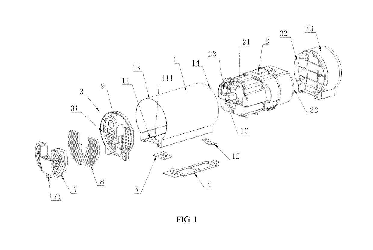
[0040]As shown in FIG. 1, the present invention provides a hand dryer, including a housing 1, a core 2 and end covers 3. The housing 1 takes the shape of a hollow tube with two ends opened, and has a first end 13 and a second end 14. The core 2 is disposed inside the housing 1, and two ends of the core 2 are disposed correspondingly to two ends of the housing 1. The end covers 3 include a first end cover 31 and a second end cover 32, and the first end cover 31 and the second end cover 32 are respectively detachably connected with two ends of the housing 1. The core 2 is fixed inside the housing 1. A shape of a cross section of the first end cover 31 is the same as a shape of an end surface of the first end 13 of the housing 1, and a shape of a cross section of the second end cover 32 is the same as a shape of an end surface of the second end 14 of the housing 1.

[0041]In this embodiment, the housing 1 takes the shape of a hollow straight tube. The shape of the end surface of the firs...


PUM

PropertyMeasurementUnit
shapeaaaaaaaaaa
diameteraaaaaaaaaa
areaaaaaaaaaaa

Abstract

A hand dryer includes a housing, a core and end covers. The housing takes the shape of a hollow tube with two ends opened, having a first end and a second end. The core is disposed inside the housing, and two ends of the core are disposed correspondingly to two ends of the housing. The end covers include a first end cover and a second end cover. The first end cover and the second end cover are respectively detachably connected with the first end and the second end of the housing. The core is fixed inside the housing, a shape of a cross section of the first end cover is the same as a shape of an end surface of the first end, and a shape of a cross section of the second end cover is the same as a shape of an end surface of the second end.

Description

CROSS REFERENCE TO RELATED APPLICATION[0001]This application claims priority to and incorporates by reference CN 201510382597.5 filed 2015 Jun. 30.BACKGROUND OF THE INVENTION[0002]Technical Field[0003]The invention relates to a hand drying equipment and, more particularly, relates to a hand dryer.[0004]Description of the Related Art[0005]Hand dryers are sanitary electric appliances for drying or blowing hands in bathrooms, and are advanced and ideal sanitary fittings and equipments. The hand dryers are generally used in hotels, restaurants, scientific research institutes, hospitals, public entertainment venues and bathrooms of families. After washing their hands, people can stretch out their hands under the air outlet of an automatic hand dryer, and then the hand dryers can automatically blow out comfortable air to dry the hands immediately. People do not need to dry their hands with towels to prevent cross infection of disease.[0006]Once an existing hand dryer is developed, the sty...

Claims


Application Information

Patent Timeline
Patent Type & Authority Patents(United States)
IPC IPC(8): A47K10/48A61L9/12
CPCA47K10/48A61L9/122A61L2209/14A61L2209/111A61L2209/13A47K2201/02
Inventor ZHENG, FUMINGWANG, JUNXIANG
Owner ZHEJIANG AIKE APPLIANCE
Why Eureka
Try Eureka