Rafter bracket

a bracket and rafter technology, applied in the field of building materials, can solve the problems of time and skill in cutting indentation, reduce the cross-sectional area of the rafter, and reduce the time and skill of cutting indentation, and achieve the effect of reducing the cross-sectional area of the rafter, and ensuring structural integrity

Active Publication Date: 2019-02-12
FOX HARDWOOD LUMBER CO LLC
View PDF22 Cites 40 Cited by
  • Summary
  • Abstract
  • Description
  • Claims
  • Application Information

AI Technical Summary

Benefits of technology

[0007]Without being bound by any particular theory, it is believed that the rafter bracket may provide a number of advantages including: 1) providing a stronger connection method of the roof system to the wall assembly; 2) allows the rafter to retain greater stru

Problems solved by technology

However, such system has a number of disadvantages, particularly if the indentation is not cut correctly, including 1) the strength of the connection o

Method used


Image

  • Rafter bracket
  • Rafter bracket
  • Rafter bracket

Examples


Embodiment Construction

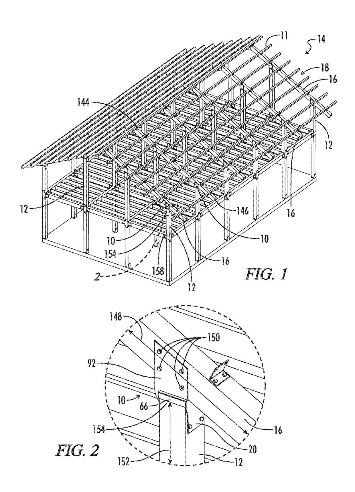
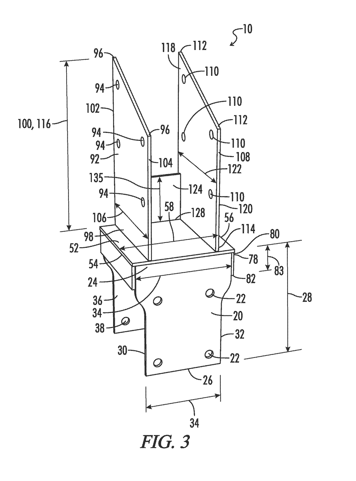
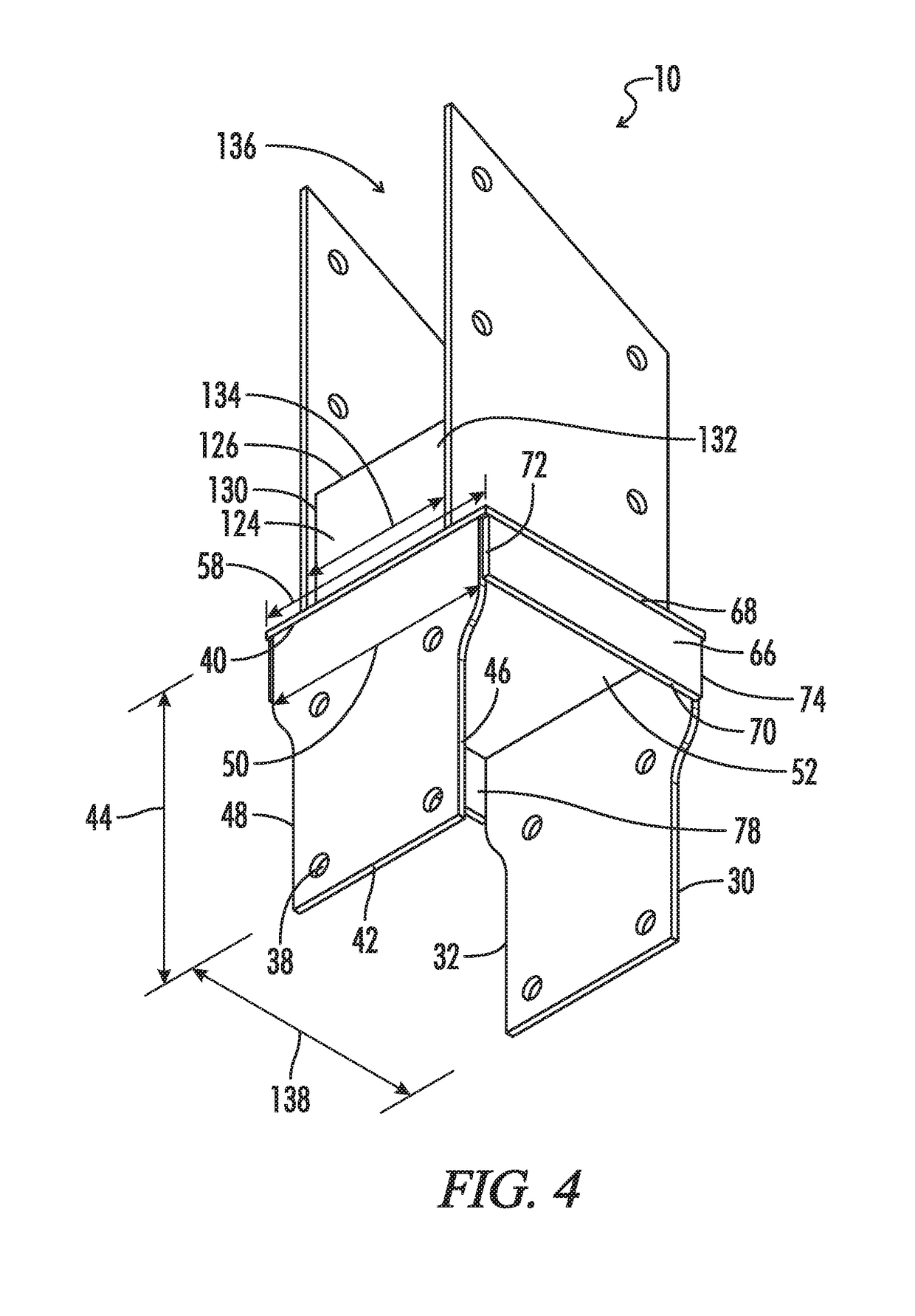
[0041]With reference to FIGS. 1-10, the present invention provides a rafter bracket generally designated by the numeral 10. In the drawings, not all reference numbers are included in each drawing for the sake of clarity. It will be understood that the above drawings are CAD drawings drawn to scale.

[0042]As shown in FIGS. 1-10, the rafter bracket 10 may be configured to connect a vertical post 12 of a building 14 to a rafter 16 of the building 14 and may include a first lower vertical side plate 20 comprising at least one first lower vertical side plate fastener aperture / hole 22, a first lower vertical side plate top 24, a first lower vertical side plate bottom 26, a first lower vertical side plate height 28 extending from the first lower vertical side plate top 24 to the first lower vertical side plate bottom 26, a first lower vertical side plate first end 30, a first lower vertical side plate second end 32 opposite the first end 30, and a first lower vertical side plate width 34 ex...


PUM


Abstract

A rafter bracket configured to connect a vertical post to a rafter and beam(s) is described herein. The rafter bracket may include lower vertical side plates, a horizontal plate, and upper vertical side plates. The horizontal plate may be perpendicular to the upper and lower vertical side plates and may separate the upper vertical side plates from the lower vertical side plates. The horizontal plate and lower vertical side plates may create a lower cavity that receives the vertical post. Meanwhile, the rafter may be positioned on one of the upper vertical side plates and positioned between two of the upper vertical side plates and may be angled at an acute angle relative to the vertical post as well as the upper and lower vertical side plates. One or more of the lower vertical side plates may receive lateral plates that define a lateral cavity receiving the beam.

Description

RELATED APPLICATIONS[0001]This application is a continuation-in-part of U.S. patent application Ser. No. 15 / 912,203, filed Mar. 5, 2018, the contents of which are incorporated by reference in their entirety.BACKGROUNDTechnical Field[0002]The present invention relates to building materials, more particularly, brackets for connecting a wooden post to a rafter for use in a post and beam and timber frame construction.Background of the Invention[0003]In light frame construction, a birdsmouth joint, also known as a bird's beak cut, is a woodworking joint that is generally used to connect a roof rafter to the top plate of a vertical post (such as a wall stud). The birdsmouth joint is an indentation cut into the rafter which consists of a “seat cut” (the face of which rests on the top plate) and a “heel cut” or “plumb cut” (the face of which lies parallel to the supporting wall), forming a shape resembling a bird's mouth. Generally, the indentation should not extend unsupported on the inter...

Claims


Application Information

Patent Timeline
IPC IPC(8): E04B1/26E04B7/04E04B7/06
CPCE04B7/045E04B1/2608E04B7/063E04B2001/2644E04B1/2604E04B2001/389
Inventor FOX, SAMUEL
Owner FOX HARDWOOD LUMBER CO LLC
Why Eureka
Try Eureka