Motor drive unit

a technology of drive unit and drive shaft, which is applied in the direction of differential gearing, belt/chain/gearing, differential gearing, etc., can solve the problems of abrupt deceleration of the vehicle, braking torque being applied to the vehicle immediately, and the electric brake cannot maintain a braking torque to stop the motion of the vehicle, etc., to achieve the effect of reverse efficiency of the feed screw mechanism to translate linear motion

Active Publication Date: 2019-02-12
TOYOTA JIDOSHA KK +1
View PDF15 Cites 1 Cited by
  • Summary
  • Abstract
  • Description
  • Claims
  • Application Information

AI Technical Summary

Benefits of technology

[0014]Thus, according to the embodiment of the present application, the drive motor serving as a prime mover of the vehicle and the differential unit for distributing torque of the drive motor may be arranged in the motor drive unit. As described, the motor drive unit further comprises the electromagnetic brake device. According to the embodiment of the present application, therefore, the electromagnetic brake device may serve as an inboard brake of the vehicle. As also described, the motor drive unit further comprises the engagement force generating device and the brake motor for actuating the engagement force generating device. According to the embodiment of the present application, therefore, rotation of the output shaft may be stopped even if current supply to the electromagnetic motor and the brake motor is stopped while halting the output shaft by actuating the engagement force generating device by the brake motor. That is, braking force can be maintained certainly in a parking vehicle even if a power source is turned off.
[0015]As described, according to the embodiment of the present application, the feed screw mechanism that translates output torque of the drive motor to the axial force to engage the brake member with the rotary member is used as the engagement force generating device. Specifically, reversed efficiency of the feed screw mechanism to translate linear motion to rotational motion is adjusted to be lower than forward efficiency to translate rotational motion to linear motion. For this reason, the axial force stopping the rotation of the output shaft can be maintained certainly. According to the embodiment of the present application, therefore, the output shaft may be kept stopping even if current supply to the electromagnetic motor and the brake motor is stopped while halting the output shaft by actuating the engagement force generating device by the brake motor.

Problems solved by technology

However, the electromagnetic brake cannot maintain a braking torque to stop a motion of a vehicle during parking while turning the power off.
In this case, however, the braking torque is applied to the vehicle immediately even if a current supply to the coil is stopped by some sort of failure during propulsion and consequently the vehicle is decelerated abruptly.
Thus, the electromagnetic brake of this kind is unsuitable to be used as the inboard brake in the motor drive unit of automobiles.

Method used


Image

  • Motor drive unit
  • Motor drive unit
  • Motor drive unit

Examples


Embodiment Construction

)

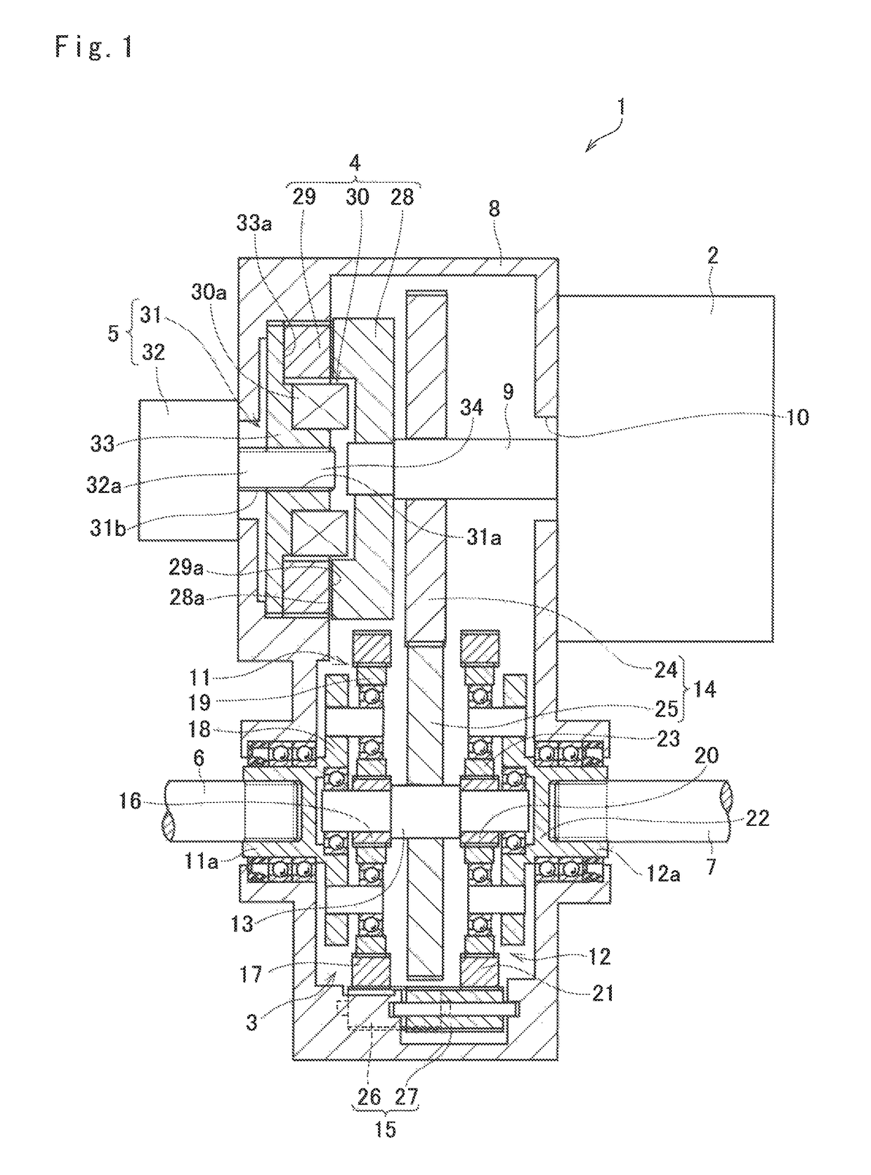
[0026]Preferred embodiments of the present application will now be explained with reference to the accompanying drawings. Referring now to FIG. 1, there is shown a preferred embodiment of the motor drive unit according to the present application. The motor drive unit shown in FIG. 1 comprises a drive motor 2, a differential unit 3, an electromagnetic brake device 4, a parking brake device 5, a first driveshaft 6 and a second driveshaft 7.

[0027]The drive motor 2 is intended to be used as a prime mover of a vehicle, and for example, a permanent magnet synchronous motor, and an induction motor may be used as the drive motor 2. The drive motor 2 is fixed to a casing 8, and an output shaft 9 of the drive motor 2 that is rotated integrally with a rotor (not shown) is inserted into the casing 8 through an insertion hole 10 so that an output torque of the drive motor 2 is delivered to the differential unit 3 through the output shaft 9.

[0028]According to the example shown in FIG. 1, the dif...


PUM


Abstract

A motor drive unit having an electromagnetic brake serving as an inboard brake that may also be used as a parking brake is provided. In the motor drive unit, output torque of a drive motor is distributed to a first driveshaft and a second driveshaft. The motor drive unit comprises: an electromagnetic brake device that stops rotation of an output shaft by contacting a brake stator to a brake rotor; a brake motor that generates torque when energized; and an engagement force generating device that generates an engagement force to engage the brake member with the rotary member when the output torque of the brake motor is applied thereto, and that maintains the engagement between the brake member and the rotary member when current supply to the electromagnetic brake device and the brake motor is stopped.

Description

CROSS REFERENCE TO RELATED APPLICATION[0001]The present invention claims the benefit of Japanese Patent Application No. 2016-029050 filed on Feb. 18, 2016 with the Japanese Patent Office, the disclosures of which are incorporated herein by reference in its entirety.BACKGROUND[0002]Field of the Invention[0003]Embodiments of the present application relate to the art of a drive motor used as a prime mover of automobiles, and especially to a motor drive unit having a power transmission device between the drive motor and drive wheels.[0004]Discussion of the Related Art[0005]PCT international publication WO 2015 / 008661 describes one example of a motor drive unit of this kind. The drive gear unit taught by WO 2015 / 008661 as a torque vectoring device comprises a differential unit for distributing torque delivered from a drive motor to right and left drive wheels, and a differential motor for controlling a torque split ratio to the drive wheels. The differential unit comprises a pair of sing...

Claims


Application Information

Patent Timeline
Patent Type & Authority Patents(United States)
IPC IPC(8): F16H48/10F16H48/36
CPCF16H48/36F16H48/10F16H2048/364F16H2048/106F16H2048/104
Inventor ISONO, HIROSHIKUBO, AIZOH
Owner TOYOTA JIDOSHA KK
Why Eureka
Try Eureka