Manufacturing of a metal component or a metal matrix composite component involving contactless induction of high-frequency vibrations

a technology of contactless induction and metal components, which is applied in the field of manufacturing of metal components or metal matrix composite components, can solve the problems of increasing cost, introducing complexity, and difficult to distribute nano-particles evenly in the alloy matrix, and achieves the effect of facilitating the control and optimization of the microstructure of the componen

Active Publication Date: 2019-02-19
EUROPEAN SPACE AGENCY
View PDF10 Cites 6 Cited by
  • Summary
  • Abstract
  • Description
  • Claims
  • Application Information

AI Technical Summary

Benefits of technology

[0004]It is an object of the present invention to provide a system and a method with which the microstructure of a component can more efficiently be controlled and optimised than with known methods; this including the obtainment of a homogeneous distribution of reinforcement in composite materials.

Problems solved by technology

One of the problems in manufacturing these alloys concerns the difficulty in distributing the nano-particles evenly in the alloy matrix, especially where large components are to be manufactured.
Furthermore, where a large volume is to be treated, multiple sonotrodes may be used, introducing complexity and increased cost.

Method used


Image

  • Manufacturing of a metal component or a metal matrix composite component involving contactless induction of high-frequency vibrations
  • Manufacturing of a metal component or a metal matrix composite component involving contactless induction of high-frequency vibrations
  • Manufacturing of a metal component or a metal matrix composite component involving contactless induction of high-frequency vibrations

Examples


Embodiment Construction

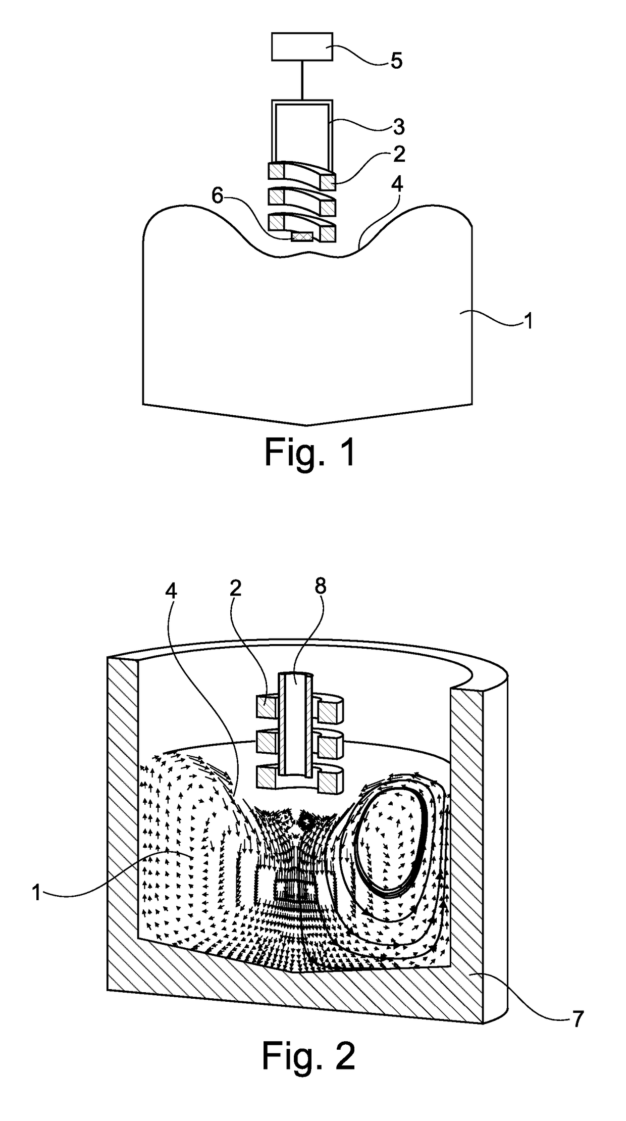
[0078]FIG. 1 shows schematically an example of a system for contactless induction of high-frequency vibrations in a volume of molten metal 1 during the manufacturing of a metal component or a metal matrix composite component. An electromagnetic primary coil 2 is moveably arranged above the volume of molten metal 1, and adjustment means 3 are used for adjusting the position of the primary coil 2 in relation to the upper free surface 4 of the molten metal 1. The curved / depressed shape of the upper free surface 4 shown in the figure results from the influence from the electromagnetic field as will be described below. The system further comprises a control unit 5 for controlling the position of the primary coil 2 to a predefined distance above and not in physical contact with the upper free surface 4 of the molten metal 1 during use of the system. The control unit 5 may be arranged close to the remainder of the system or at a distance therefrom. It will typically comprise a computer (no...


PUM

PropertyMeasurementUnit
sizeaaaaaaaaaa
frequenciesaaaaaaaaaa
currentaaaaaaaaaa

Abstract

The present invention relates to a system for contactless induction of high-frequency vibrations in a volume of molten metal during the manufacturing of a metal component or a metal matrix composite component. The system includes a moveably arranged electromagnetic primary coil, adjustment means for adjusting the position of the primary coil, and a control unit for controlling the position of the primary coil to a predefined distance above, but not in contact with, an upper free surface of the molten metal. The molten metal may be contained in a foundry crucible during manufacturing. The system can be used as an additive manufacturing system, with the primary coil arranged above the melt pool. A secondary low-frequency electromagnetic coil may be arranged around and at a distance from the molten metal to induce flow and / or vibrations in the molten metal.

Description

FIELD OF THE INVENTION[0001]The present invention relates to the manufacturing of a metal component or a metal matrix composite component by use of a system and a method involving contactless induction of high-frequency vibrations in a volume of molten metal during the manufacturing.BACKGROUND OF THE INVENTION[0002]Within the technology of casting of metals it is known to apply magnetic fields to the molten metal during manufacturing; this is known as electromagnetic stirring. U.S. Pat. No. 4,523,628 and U.S. Pat. No. 6,443,219 disclose manufacturing methods in which electromagnetic coils are arranged so that they surround the mould at areas where the generated magnetic fields can influence the metal during solidification by generating vibrations in the metal that can result in an improved homogeneous structure.[0003]Application of vibrations during manufacturing in order to improve the microstructure are also known in relation to Metal-Matrix-Nano-Composites (MMNCs) which are alloy...

Claims


Application Information

Patent Timeline
Patent Type & Authority Patents(United States)
IPC IPC(8): B22D27/08B22D1/00B22D19/14B22D19/16B22D27/02B22F3/105C21C5/52C21C7/00C22C32/00C22C33/04C22C47/08B33Y10/00B33Y30/00B82Y30/00
CPCB22D27/08B22D19/14B22D19/16B22D27/02B22F3/1055C21C5/5241C21C7/0037C22C32/0015C22C32/0063C22C32/0068C22C33/04C22C47/08B22D1/00Y02P10/295B22F2003/1056B33Y10/00B33Y30/00B82Y30/00Y02P10/253Y02P10/25B22F12/00B22F12/90B22F10/50B22F10/38B22F10/25
Inventor JARVIS, DAVID JOHNPERICLEOUS, KOULISBOJAREVICS, VALDISLEHNERT, CHRISTIAN
Owner EUROPEAN SPACE AGENCY
Why Eureka
Try Eureka