Combination of RFID antenna and illumination device

a technology of illumination device and rfid antenna, which is applied in the field of combination of rfid antenna and illumination device, can solve the problems of easy breakage and reading rang

Inactive Publication Date: 2019-02-19
LAI CHUNG PING
View PDF4 Cites 17 Cited by
  • Summary
  • Abstract
  • Description
  • Claims
  • Application Information

AI Technical Summary

Problems solved by technology

However, when the antenna of the RFID reader is mounted on the entrance the supermarket, it is broken easily.
When the antenna of the RFID reader is mounted on the ceiling of the supermarket, a reading range is limited because of a height of the ceiling.

Method used


Image

  • Combination of RFID antenna and illumination device
  • Combination of RFID antenna and illumination device
  • Combination of RFID antenna and illumination device

Examples


first embodiment

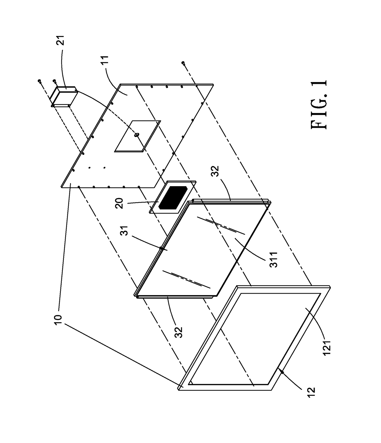
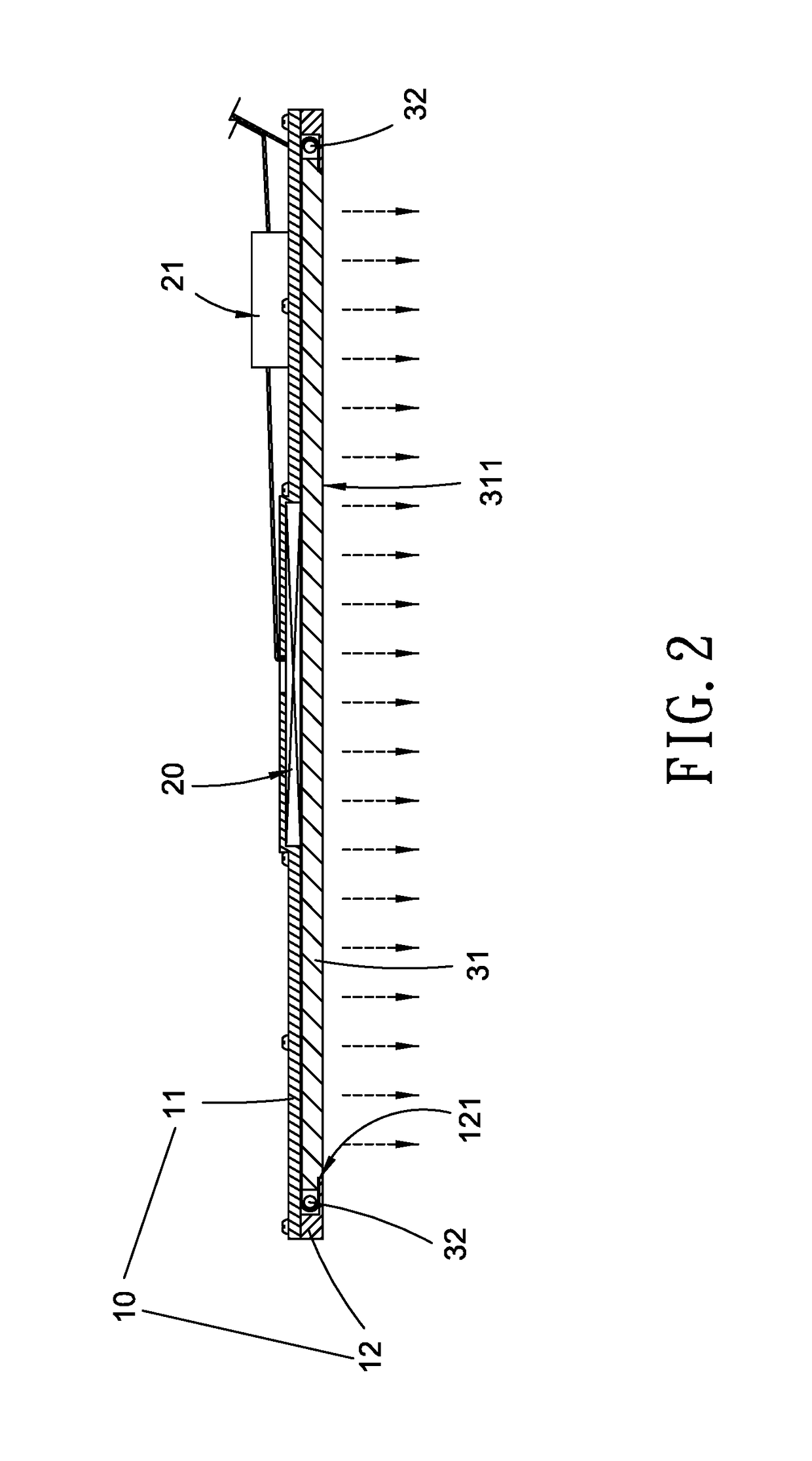
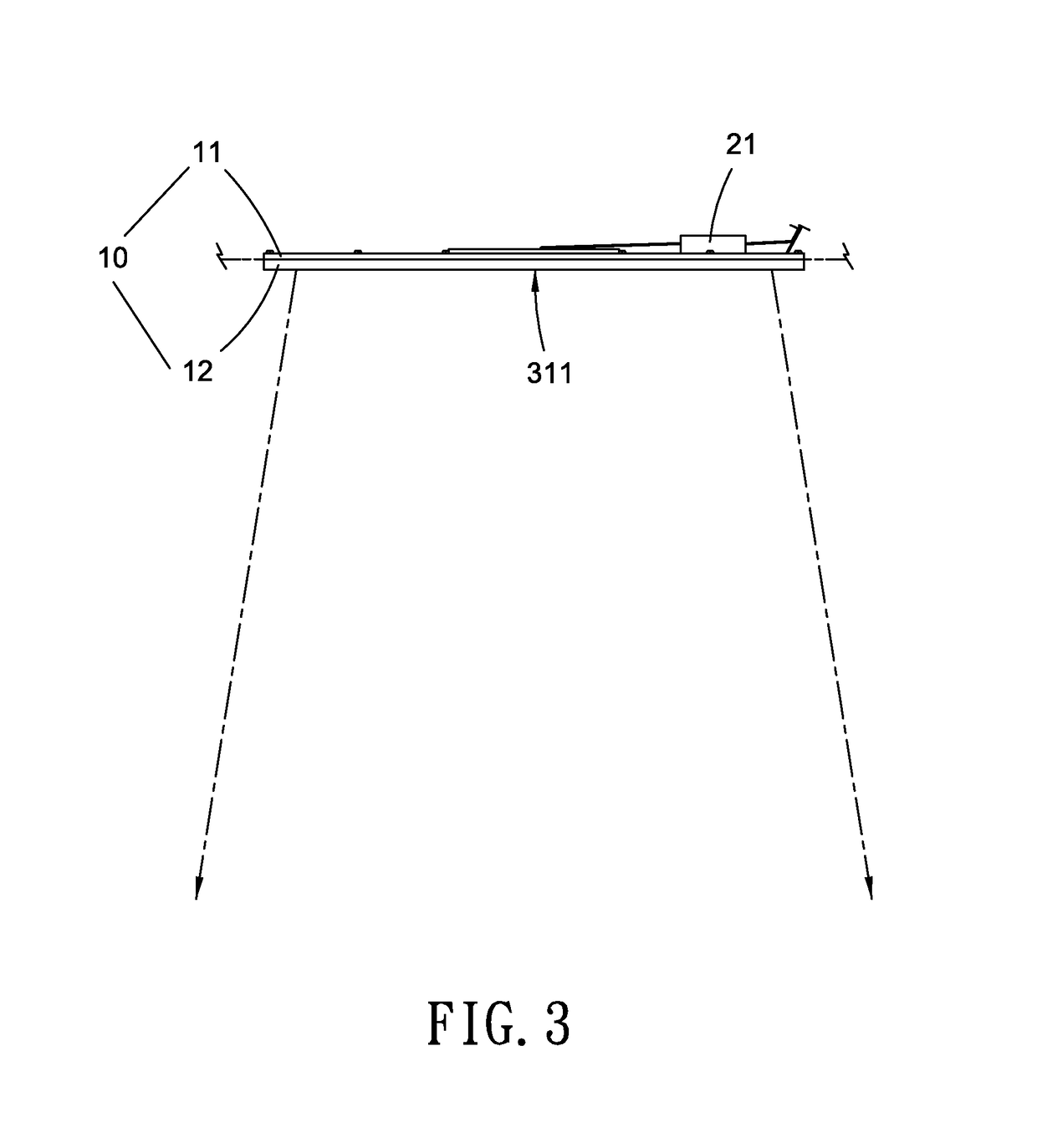
[0023]With reference to FIGS. 1 and 2, a combination of a RFID antenna and an illumination device according to the present invention comprises: a casing 10, a lighting unit, and the RFID antenna 20.

[0024]The casing 10 includes a metal plate 11 and a fixing frame 12, wherein the fixing frame 12 has an opening 121 configured to transport lights from the lighting unit, and the fixing frame 12 is mounted on a front end of the metal plate 11. Preferably, the metal plate 11 is made of aluminum.

[0025]The lighting unit includes a light guide plate 31 and multiple light emitting elements 32 arranged on a peripheral side of the light guide plate 31, wherein each of the multiple light emitting elements 32 is light-emitting diode (LED) or a LED light tube, the lighting unit is defined between the metal plate 11 and the fixing frame 12, and the light guide plate 31 is fixed between the metal plate 11 and the fixing frame 12, wherein the light guide plate 31 has a transporting face 311 facing the...

second embodiment

[0031]Referring to FIG. 6, the camera 41 and the controller 42 are respectively mounted on two sides of the metal plate 11 below the ceiling, and the camera 41 is a mini digital camera, wherein an image taking range of the camera 41 is adjustably used as the lights illumination area of the lighting unit, hence the combination of the second embodiment is applicable for product security, image monitoring, access control systems, and location tracking. For example, the RFID reader 21 starts the controller 42 after acquiring the radio identification signal of the tag by way of the RFID antenna 20 so that the controller 42 controls the camera 41 to take images and to send the images to a host / server via the wireless communication module of the controller 42.

[0032]Preferably, power supply and / or wiring of the lighting unit, the RFID reader 21, and the Wi-Fi monitoring unit are integrated together so as to simplify power and signal wirings.

[0033]In another embodiment, the RFID reader 21 tr...


PUM

PropertyMeasurementUnit
areaaaaaaaaaaa
heightaaaaaaaaaa
heataaaaaaaaaa

Abstract

A combination of a RFID antenna and an illumination device contains: a casing, a lighting unit, and a RFID antenna. The casing includes a metal plate and a fixing frame which has an opening and being mounted on a front end of the metal plate. The lighting unit includes a light guide plate and multiple light emitting elements, wherein the lighting unit is defined between the metal plate and the fixing frame, the light guide plate is fixed between the metal plate and the fixing frame, and the light guide plate has a transporting face facing the opening of the fixing frame so that the lights illuminate to the transporting face of the light guide plate from the multiple light emitting element. The RFID antenna is accommodated in the front end of the metal plate and is defined between the light guide plate and the metal plate.

Description

FIELD OF THE INVENTION[0001]The present invention relates to a combination of a RFID antenna and an illumination device which overlaps a light illumination area of the lighting unit with the reading range of the RFID antenna so that user distinguishes the reading range of the RFID antenna by using the lights illumination area of the lighting unit.BACKGROUND OF THE INVENTION[0002]A conventional radio frequency identification system contains a tag and a RFID reader, wherein the tag is configured to store data, and the RFID reader transmits radio waves (i.e. electromagnetic waves) so that the tag electromagnetically receives and converts electromagnetic waves into electric currents within a receiving range, and a chip in the tag operates by using the electric current and transmits the data to the RFID reader via the radio identification signals of the tag. Thereafter, the RFID reader reads data in the radio identification signals from the tag and provides the data to an application sys...

Claims


Application Information

Patent Timeline
Patent Type & Authority Patents(United States)
IPC IPC(8): G06K7/10H01F38/14H01Q1/38H01Q1/06H04N5/232G08B13/24H04W84/12
CPCG06K7/10118H01F38/14H01Q1/38H01Q1/06H04N5/23203G06K7/10425G08B13/2417G08B13/248H04W84/12H01Q1/2225H01Q1/2291H04N23/66
Inventor LAI, CHUNG-PING
Owner LAI CHUNG PING
Why Eureka
Try Eureka