Body weight resistance rowing simulator exercise machine with a force reduction transmission

a technology of force reduction transmission and exercise machine, which is applied in the field of exercise, physical fitness and physical therapy equipment and machines, can solve the problems of increasing the amount of wear components, adding additional costs to the production of these products, and requiring additional maintenance, so as to improve the strength and cardiovascular conditioning of users, the effect of compelling and fun use, and cost-effective machine manufacturing and maintenan

Active Publication Date: 2019-03-05
PROD DESIGN INNOVATIONS LLC
View PDF37 Cites 4 Cited by
  • Summary
  • Abstract
  • Description
  • Claims
  • Application Information

AI Technical Summary

Benefits of technology

[0018]The present invention provides features and advantages not previously available in prior art rowing simulator exercise machines. Those features and advantages include a forward pivoting user support frame that houses a sliding user seat whereas the angle of the user seat changes as it slides on the pivoting user support causing the angle of the user's torso to vary relative to the floor and the elevation of the user's hips relative to the user's feet to vary during operation of the machine, said forward pivoting user support frame and the user's body weight also provide the resistance to the exercise motion eliminating the need for an additional resistance producing mechanism. By eliminating the need for a separate resistance mechanism, the present invention creates a more cost effective machine to manufacture and maintain. The present invention provides a substantial amount of concentric and eccentric resistance to the rowing exercise motion so as to improve the user's strength and cardiovascular conditioning. The present invention also provides a lifting or lowering while sliding exercise motion that is compelling and fun to use so as to motivate the user to increase their frequency and duration of use as a part of reaching his or her health and fitness goals.

Problems solved by technology

These force resisting mechanical assemblies add additional cost to producing these products, they require additional maintenance and increase the amount of wear components.
Furthermore, these additional resistance components increase the manufacturing cost and the amount of wear items in the machine.
This machine also keeps the angular orientation of the user seat constant relative to the floor throughout the range of motion which makes it more challenging to achieve the correct torso angle at the fully extended range of motion.
Furthermore, this additional resistance component increases the manufacturing cost and the amount of wear items in the machine.
This machine also keeps the angular orientation of the user seat constant relative to the floor throughout the range of motion which makes it more challenging to achieve the correct torso angle at the fully extended range of motion.
The Edmondson '326 machine is designed to eliminate the spring or elastic cable component that returns the pulling handle to the start position and replace it with a gravity fed return force but said gravity fed force is not adequate or intended to provide the amount of resistance required for the concentric pulling motion of the exercise.
As with other flywheel resisted devices, Edmondson '326 teaches foot straps that allow the user's legs to assist with the return force of the pulling chain further emphasizing that the return force of the pulling chain is not designed to provide significant concentric or eccentric resistance to the exercise movement.
Edmondson '326 also teaches an optimal handle return force of a constant 7 pounds that is designed to take up the slack of the handle pull chain during the return motion of the exercise but would not provide adequate resistance to even the most deconditioned user during the pulling motion of the exercise.

Method used


Image

  • Body weight resistance rowing simulator exercise machine with a force reduction transmission
  • Body weight resistance rowing simulator exercise machine with a force reduction transmission
  • Body weight resistance rowing simulator exercise machine with a force reduction transmission

Examples


Embodiment Construction

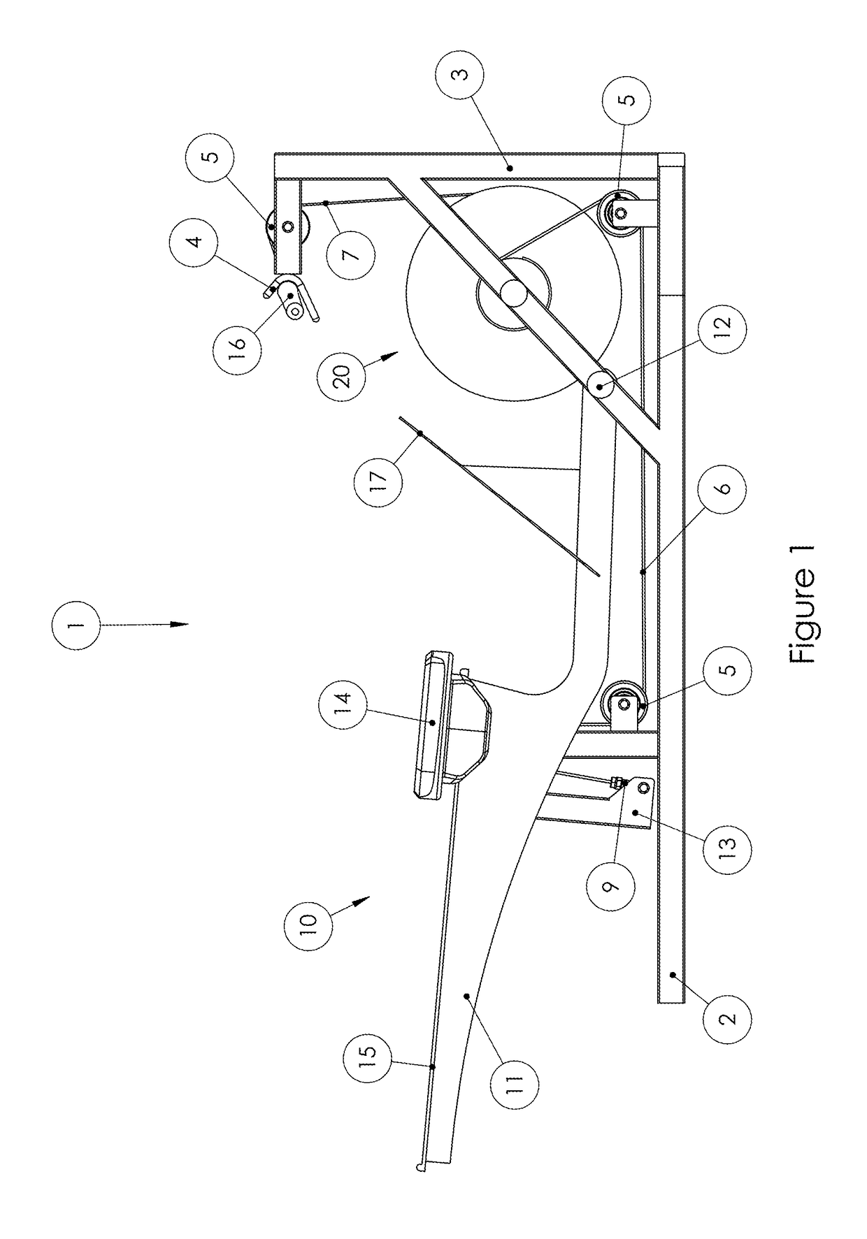
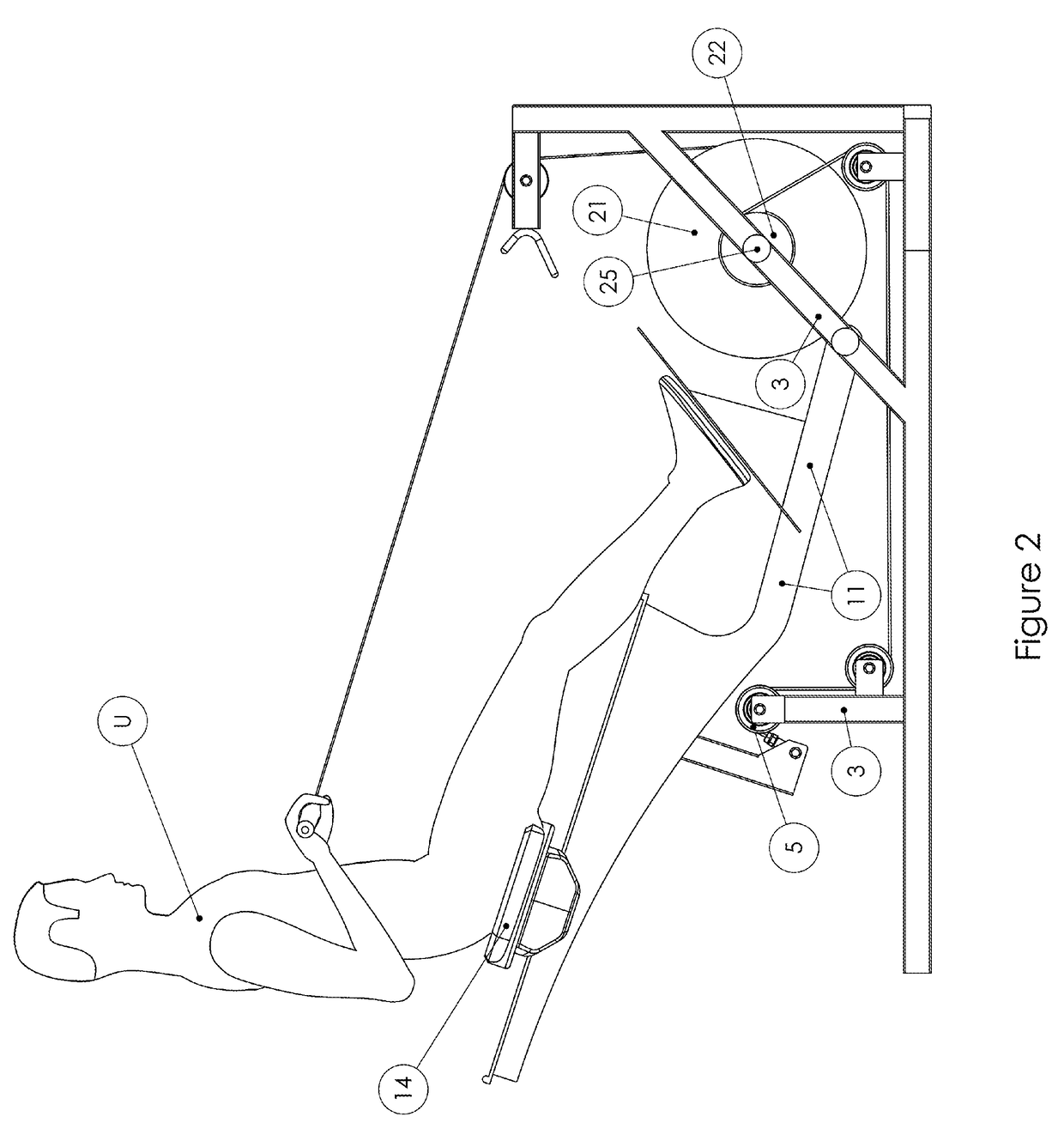
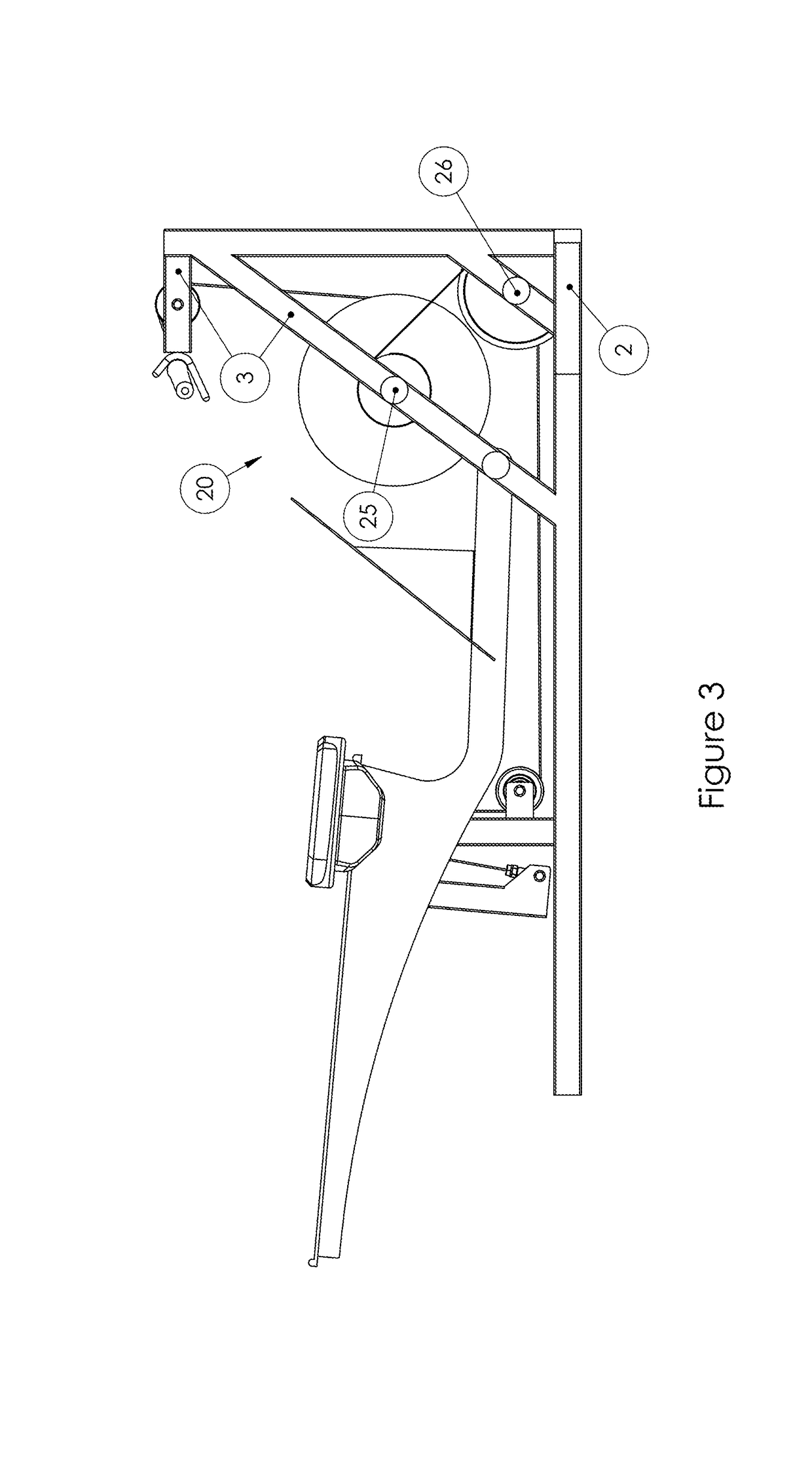
[0043]Exemplary preferred embodiments are disclosed below in connection with the attached drawings. Throughout this specification and disclosure, various terms will be used to describe various elements or sets of elements, features or sets of features, and devices or sets of devices. For example, the term forward end or portion of the machine would refer to the end or portion of the machine most proximal to the pivotally connected end of the moveable user support frame assembly. The term rearward end or portion of the machine would refer to the end or portion of the machine most distal to the pivotally connected end of the moveable user support frame assembly. The term user support frame assembly or movable user support frame assembly will be used to describe the rigid pivoting frame that the seat rolls upon combined feet support surface. The term base frame will be used to describe the stationary horizontal rigid portion of the frame that contacts the floor combined with angular an...


PUM


Abstract

A user weight resisted rowing exercise simulation machine with a movable user support pivotally connected to a forward portion of a stationary horizontal base frame and a slidable seat and rigid feet support mounted to the movable user support frame and a pulling handle operatively connected to the movable user support frame such that moving the pulling handle towards the rearward portion of the machine causes the rearward portion of the user support frame to pivot upward and moving the pulling handle away from the rearward portion of the machine causes the rearward portion of the movable user support to pivot downward and the force required to move the pulling handle towards the rearward portion of the machine is reduced and controlled by the operative connection of the pulling handle to the user support frame.

Description

STATEMENT OF RELATED APPLICATIONS[0001]This application claims priority on and the benefit of U.S. Provisional Patent Application No. 62 / 437,518 having a filing date of 21 Dec. 2016 and U.S. Provisional Patent Application No. 62 / 517,372 having a filing date of 9 Jun. 2017.BACKGROUND OF THE INVENTION[0002]Technical Field[0003]This invention relates to the general technical field of exercise, physical fitness and physical therapy equipment and machines. This invention relates more specifically to the field of cardiovascular and strength conditioning rowing exercise simulator machines wherein the weight of the user plus a movable user support provides the resistance to the exercise motion and does not require a separate resistance source.[0004]Prior Art[0005]Exercise, physical fitness and physical therapy equipment and machines are available in various configurations and for various purposes, and are available for all of the major muscle groups. Most of these machines and equipment, es...

Claims


Application Information

Patent Timeline
Patent Type & Authority Patents(United States)
IPC IPC(8): A63B21/00A63B21/22A63B22/00A63B23/035A63B23/04A63B23/12A63B21/068
CPCA63B22/0076A63B21/00069A63B21/00181A63B21/068A63B21/155A63B21/22A63B22/0046A63B23/03575A63B23/0405A63B23/1209A63B21/4035A63B2208/0228A63B2022/0079A63B21/225
Inventor ELLIS, JOSEPH K.AGUILAR, JOSHUA M.
Owner PROD DESIGN INNOVATIONS LLC
Why Eureka
Try Eureka