Method of recognizing conveyor belt wear condition

a technology of wear condition and conveyor belt, which is applied in the field of recognizing the wear condition of conveyor belts, can solve the problems of large deviation between the actual wear resistance of the conveyor belt the wear resistance obtained by these conventional evaluation methods, and the wear condition of the upper cover rubber at the use site, so as to achieve accurate recognition, high correlation between apparent compressive stress and the amount of wear per unit frictional energy, and high degree of frictional energy

Active Publication Date: 2019-03-05
THE YOKOHAMA RUBBER CO LTD
View PDF8 Cites 5 Cited by
  • Summary
  • Abstract
  • Description
  • Claims
  • Application Information

AI Technical Summary

Benefits of technology

[0004]The present technology provides a method of recognizing a conveyor belt wear condition where a wear condition of an upper cover rubber at a use site can be accurately recognized based on the results of a wear resistance evaluation test using a sample.
[0008]In rubber subject to friction, a correlation between rubber surface roughness and apparent compressive stress generated by a pressing force provided on the rubber is high, and a correlation between rubber surface roughness and amount of wear per unit frictional energy of rubber subject to friction is high. Therefore, a correlation between apparent compressive stress and amount of wear per unit frictional energy is also high. Therefore, with the former method of recognizing a conveyor belt wear condition according to the present technology, a wear condition of an upper cover rubber at a use site can be accurately recognized based on a database showing a correlation between the surface roughness, the apparent compressive stress, and the amount of wear per unit frictional energy, and based on the apparent compressive stress generated on the upper cover rubber cover at a conveyor belt use site.
[0009]Furthermore, in rubber subject to friction, a correlation between viscoelastic properties of the rubber and average wear pitch calculated from the rubber surface roughness is high, and a correlation between an actual amount of wear of rubber and average wear pitch is high. Therefore, a correlation between viscoelastic properties of the rubber and actual amount of wear is also high. Therefore, with the latter method of recognizing a conveyor belt wear condition according to the present technology, a wear condition of an upper cover rubber at a use site can be accurately recognized based on a database showing a correlation between the average wear pitch, the viscoelastic properties, and the actual amount of wear, and based on the viscoelastic properties of the upper cover rubber of the conveyor belt, and based on an average wear pitch of the upper rubber cover.

Problems solved by technology

When the object to be conveyed is loaded on the upper cover rubber and conveyed, the upper cover rubber is subject to wear as a result of the object to be conveyed sliding on the upper cover rubber.
However, the wear resistance obtained by these conventional evaluation methods and actual wear resistance of a conveyor belt at a use site greatly deviate.
Therefore, evaluation methods using a rubber sample have a problem where a wear condition of a conveyor belt at a use site can not be accurately recognized.
Furthermore, in rubber subject to friction, a correlation between viscoelastic properties of the rubber and average wear pitch calculated from the rubber surface roughness is high, and a correlation between an actual amount of wear of rubber and average wear pitch is high.
Therefore, a correlation between viscoelastic properties of the rubber and actual amount of wear is also high.

Method used


Image

  • Method of recognizing conveyor belt wear condition
  • Method of recognizing conveyor belt wear condition
  • Method of recognizing conveyor belt wear condition

Examples


Embodiment Construction

[0022]A method of recognizing a conveyor belt wear condition according to the present technology will be described below based on embodiments illustrated in the drawings.

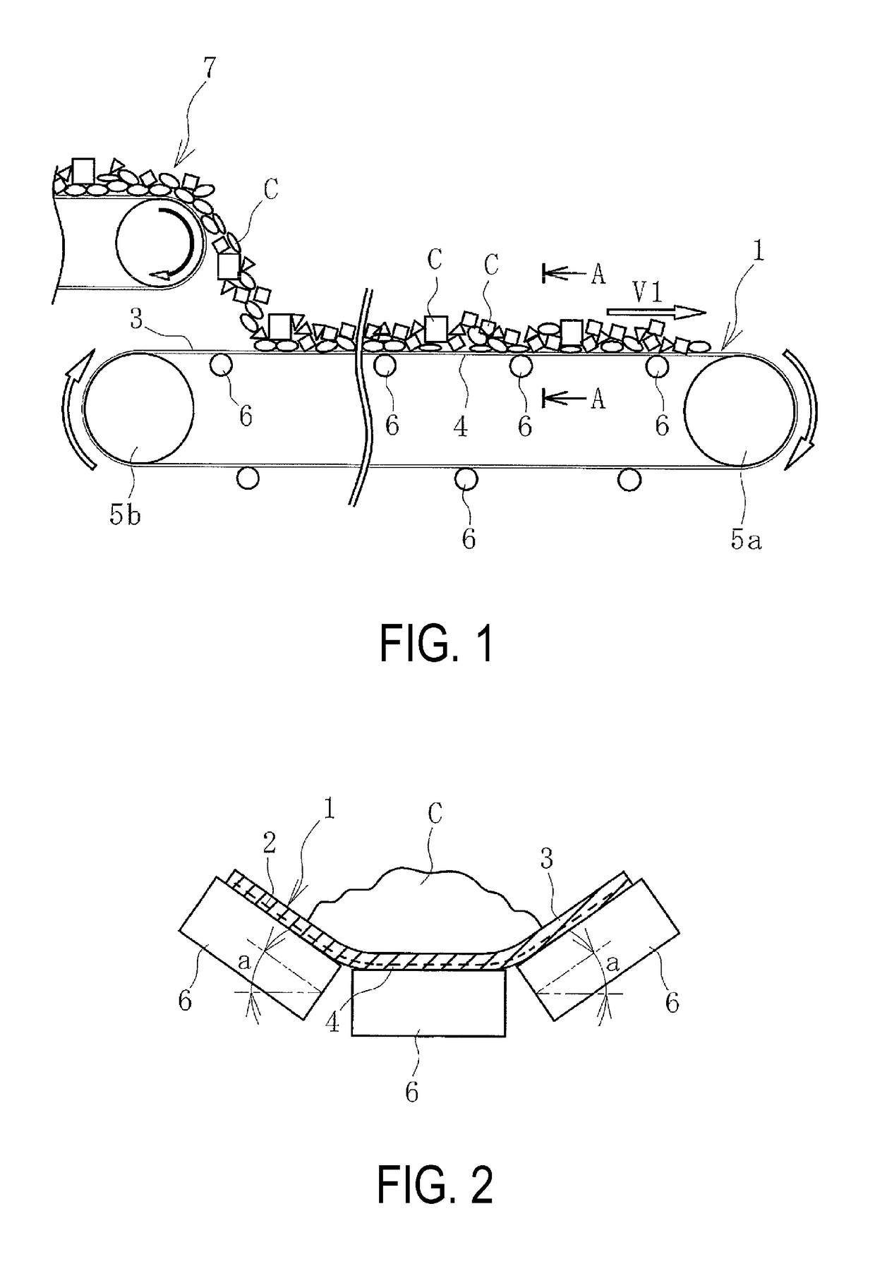
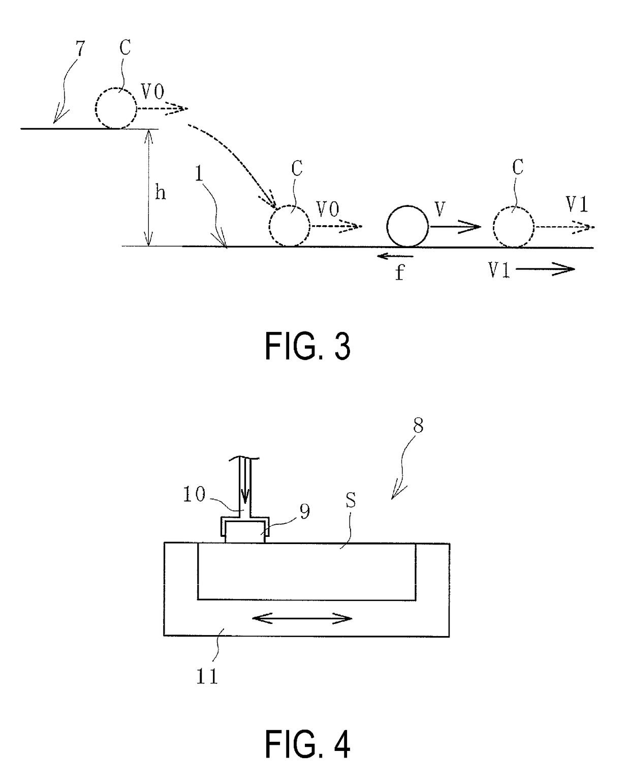
[0023]In a conveyor belt line illustrated in FIG. 1, an object to be conveyed C conveyed by another conveyor belt 7 is fed onto a conveyor belt 1 and conveyed to a conveying destination by the conveyor belt 1. The object to be conveyed C may be fed onto the conveyor belt 1 by a hopper or the like. The conveyor belt 1 is stretched at a predetermined tension between pulleys 5a and 5b.

[0024]As illustrated in FIG. 2, the conveyor belt 1 is configured from: a core layer 2 formed from a core as canvas, steel cord, or the like; and an upper cover rubber 3 and a lower cover rubber 4 that sandwich the core layer 2. The core layer 2 is a member bearing a tension that stretches the conveyor belt 1. The lower cover rubber 4 is supported by a support roller 6 on a carrier side of the conveyor belt 1, and the upper cover rubber ...


PUM

PropertyMeasurementUnit
compressive stress Peaaaaaaaaaa

Abstract

A method of recognizing a conveyor belt wear condition is provided. Relationships between an apparent compressive stress in a wear resistance test and surface roughness of a sample and between the surface roughness and amount of wear per unit frictional energy of the sample are acquired. A wear condition of an upper cover rubber is recognized based on an apparent compressive stress generated on the upper cover rubber at a use site, and a database is created based on the relationships. Alternatively, relationships between an average wear pitch calculated from the surface roughness and viscoelastic properties of the sample and between the average wear pitch and an actual amount of wear of the sample are acquired. A wear condition of the upper cover rubber is recognized based on the viscoelastic properties of the upper cover rubber of the use site and a database is created based on the relationships.

Description

TECHNICAL FIELD[0001]The present technology relates to a method of recognizing a conveyor belt wear condition, and particularly relates to a method of recognizing a conveyor belt wear condition where a wear condition of an upper cover rubber at a conveyor belt use site can be accurately recognized based on the results of a wear resistance evaluation test using a sample.BACKGROUND ART[0002]Various objects including iron ore, limestone, and other mineral resources are conveyed by conveyor belts. When being conveyed by the conveyor belt, an object to be conveyed is fed onto an upper cover rubber of the conveyor belt from a hopper or another conveyor belt. The fed object to be conveyed is loaded on the upper cover rubber and conveyed in a traveling direction of the conveyor belt. When the object to be conveyed is loaded on the upper cover rubber and conveyed, the upper cover rubber is subject to wear as a result of the object to be conveyed sliding on the upper cover rubber. The amount ...

Claims


Application Information

Patent Timeline
Patent Type & Authority Patents(United States)
IPC IPC(8): B65G43/02G01N3/56B65G43/00
CPCB65G43/02G01N3/56B65G2207/48B65G2203/0275
Inventor HOU, GANGZOU, DEQINGONO, KAZUNORIKONO, SAKIKO
Owner THE YOKOHAMA RUBBER CO LTD
Why Eureka
Try Eureka