Turbine blade having a shroud and a cutting tooth

a turbine blade and shroud technology, applied in the direction of blade accessories, engine components, leakage prevention, etc., can solve the problems of reducing the efficiency of the turbine, and achieve the effects of less weight, improved sealing coverage, and greater axial distan

Active Publication Date: 2019-03-05
MTU AERO ENGINES GMBH
View PDF7 Cites 0 Cited by
  • Summary
  • Abstract
  • Description
  • Claims
  • Application Information

AI Technical Summary

Benefits of technology

[0017]In several embodiments of the present invention, the term “stiffening element” is understood to mean a structural element by means of which greater stiffness is achieved for the respective portion surrounding the stiffening element or for the entire component as compared, for example, to a portion or component without a stiffening element. Greater stiffness may result in greater strength and / or greater stability of the component. Furthermore, a stiffening element may be used to optimize dynamic properties of the respective portion or of the entire component. The stiffening may, for example, cause a change in the vibration characteristics, such as shifts in the resonant frequency or in the natural frequency. The natural frequency may be shifted to vibration frequency ranges further away from the operating point and / or design point of the component. By using a stiffening element, critical vibrations can be prevented or reduced.
[0023]Advantageously, the turbine blade according to the present invention may allow for a greater axial distance between the sealing tips (of the sealing lip) for the same shroud cutback, which enables improved coverage of the seal in the event of large axial displacements.
[0024]Advantageously, the turbine blade according to the present invention may have less weight than prior art turbine blades.
[0025]Due to an inclined sealing lip in combination with the cutting tooth, the turbine blade of the present invention may advantageously have reduced seal leakage.
[0026]The integrally formed part, where the surfaces of the cutting tooth, the sealing lip of the shroud and the extended cutting tooth or airfoil merge into one another, may advantageously eliminate the need for an accumulation of mass at the airfoil leading edge (in the main direction of flow incidence on the airfoil).

Problems solved by technology

These are intended to prevent the medium passing through the turbines from flowing past the radially outer edge of the turbine blade, which would reduce the efficiency of the turbine.

Method used


Image

  • Turbine blade having a shroud and a cutting tooth
  • Turbine blade having a shroud and a cutting tooth
  • Turbine blade having a shroud and a cutting tooth

Examples


Embodiment Construction

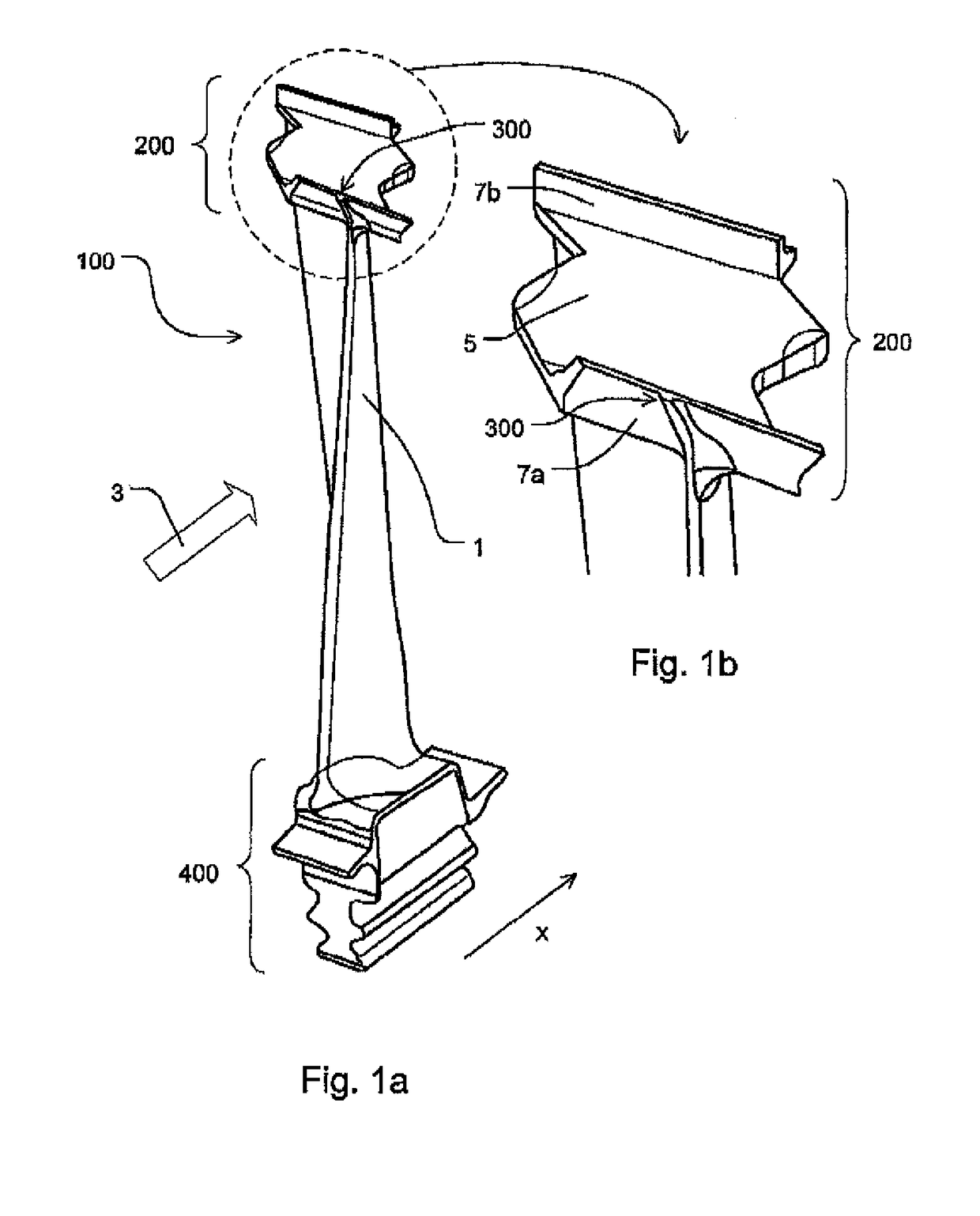
[0033]FIG. 1a depicts, in a simplified schematic perspective view, a turbine blade 100 according to the present invention, including a shroud 200, a cutting tooth 300, an airfoil 1 and a main direction of flow incidence 3 extending in the x-direction.

[0034]Shroud 200 is located at the radial end of airfoil 1.

[0035]The entire turbine blade 100 including shroud 200, cutting tooth 300, and a blade root 400 may be manufactured as a casting.

[0036]FIG. 1b is a detail of FIG. 1a, showing an enlarged view of the radial end portion of the turbine blade 100 according to the present invention, including shroud 200 and cutting tooth 300.

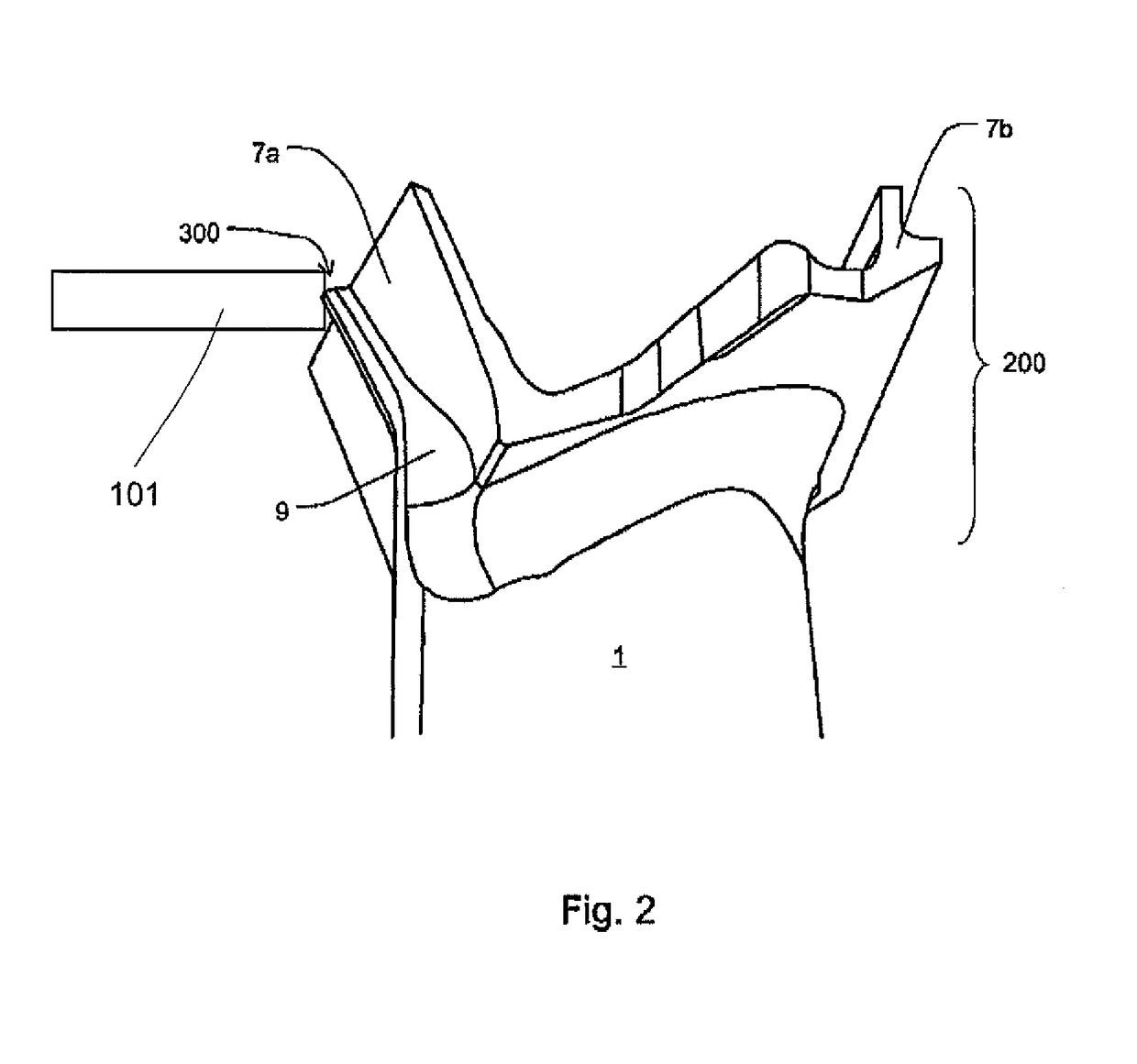
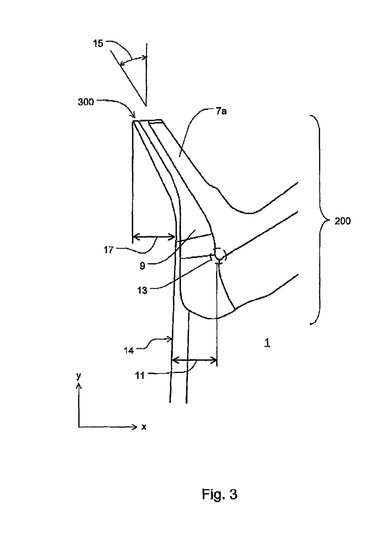
[0037]Shroud 200 has a top surface 5, which is bounded by a sealing lip 7a located upstream (with respect to the main direction of flow; i.e., in the x-direction) and a downstream trailing sealing lip 7b. Sealing lips 7a, 7b are intended to prevent the medium passing through from flowing past the radially outer edge of turbine blade 100 between the turbine blade...


PUM


Abstract

A turbine blade (100) having an airfoil (1). In its radially outer region, the turbine blade (100) has at least one shroud (200) or at least one shroud segment, as well as at least one cutting tooth (300) which is intended to engage at least once into portions of a turbine casing during use of the turbine blade (100). The cutting tooth (300) is connected to the shroud (200) or the shroud segment.

Description

[0001]This claims the benefit of European Patent Application No. 12 198 862.0, filed Dec. 21, 2012 and hereby incorporated by reference herein.[0002]The present invention relates to a gas turbine blade, in particular a turbine blade having an airfoil, a shroud or a shroud segment, and a cutting tooth.BACKGROUND[0003]In the art, there are known turbine blades having airfoils provided with shrouds having sealing lips. These are intended to prevent the medium passing through the turbines from flowing past the radially outer edge of the turbine blade, which would reduce the efficiency of the turbine.SUMMARY OF THE INVENTION[0004]It is an object of the present invention to provide a further turbine blade having an airfoil, a shroud or a shroud segment.[0005]The present invention provides a turbine blade having an airfoil which has a shroud or a shroud segment at or in the radially outer region. In this radially outer region, the turbine blade further has at least one cutting tooth which ...

Claims


Application Information

Patent Timeline
Patent Type & Authority Patents(United States)
IPC IPC(8): F01D5/20F01D5/22F01D11/12
CPCF01D5/20F01D5/225F01D11/125F01D11/122F05D2240/304F05D2240/303
Inventor BOECK, ALEXANDERFELDMANN, MANFREDWILLIAMS, STEPHEN ROYSTON
Owner MTU AERO ENGINES GMBH
Why Eureka
Try Eureka