Vehicle with wheel-end disconnect and associated control method

a technology of wheel-end disconnect and associated control method, which is applied in the direction of control devices, auxiliary drives, and compacts, can solve the problems of increasing fuel consumption, and achieve the effect of reducing parasitic losses

Active Publication Date: 2019-03-05
FORD GLOBAL TECH LLC
View PDF12 Cites 0 Cited by
  • Summary
  • Abstract
  • Description
  • Claims
  • Application Information

AI Technical Summary

Benefits of technology

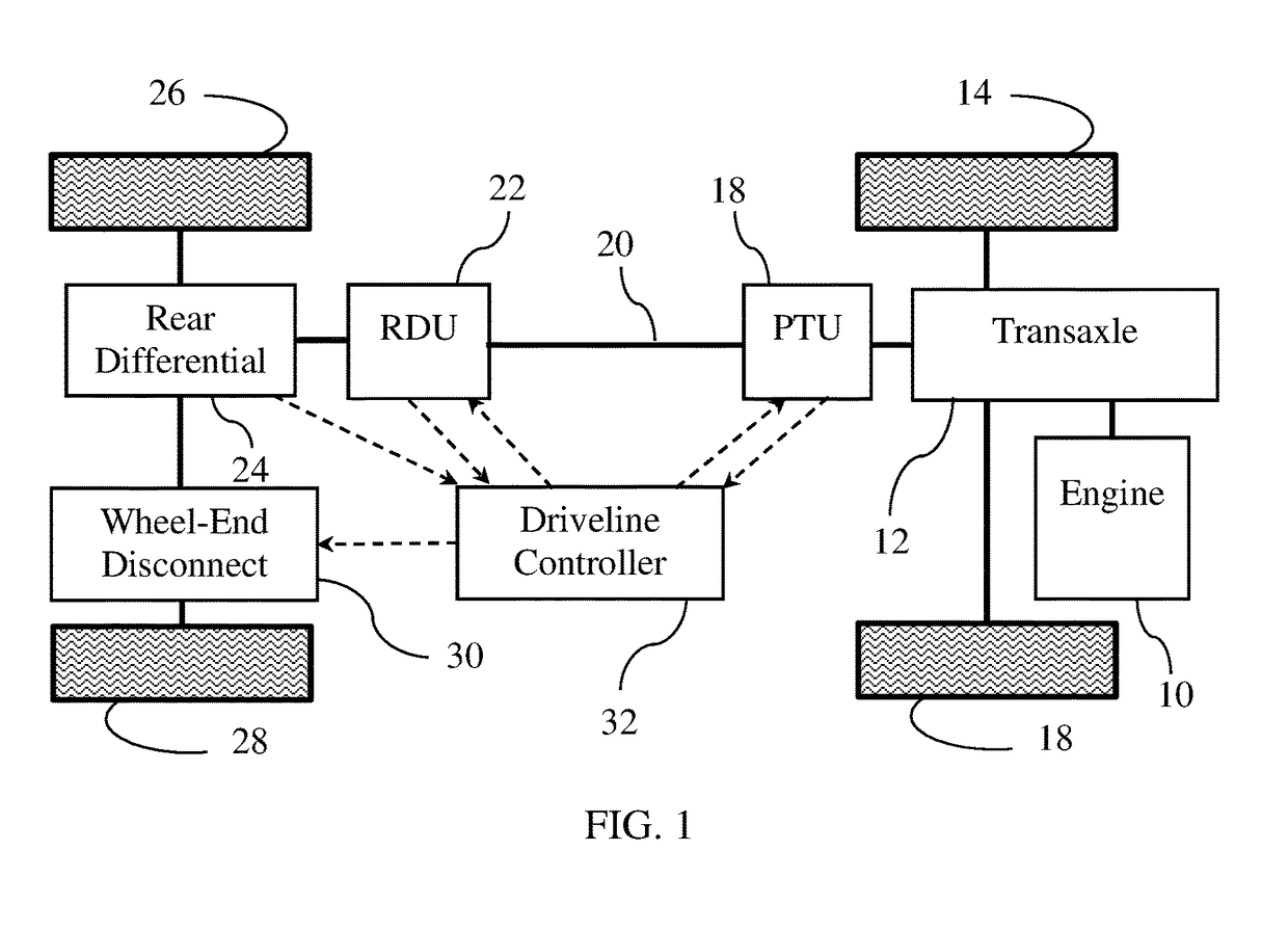
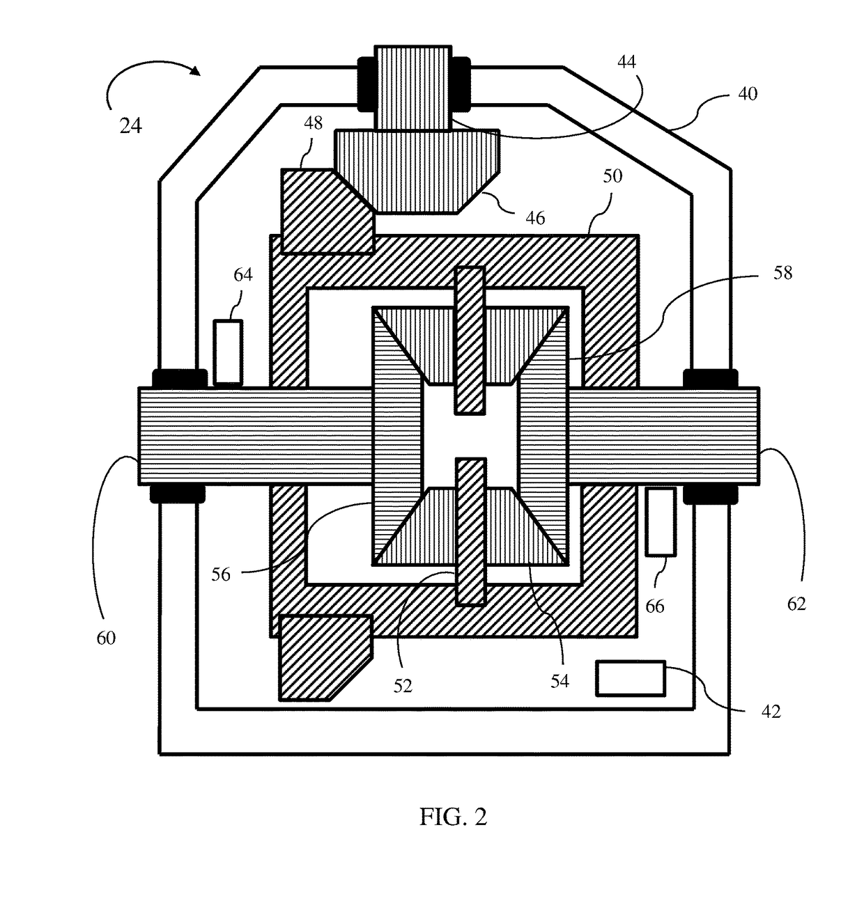
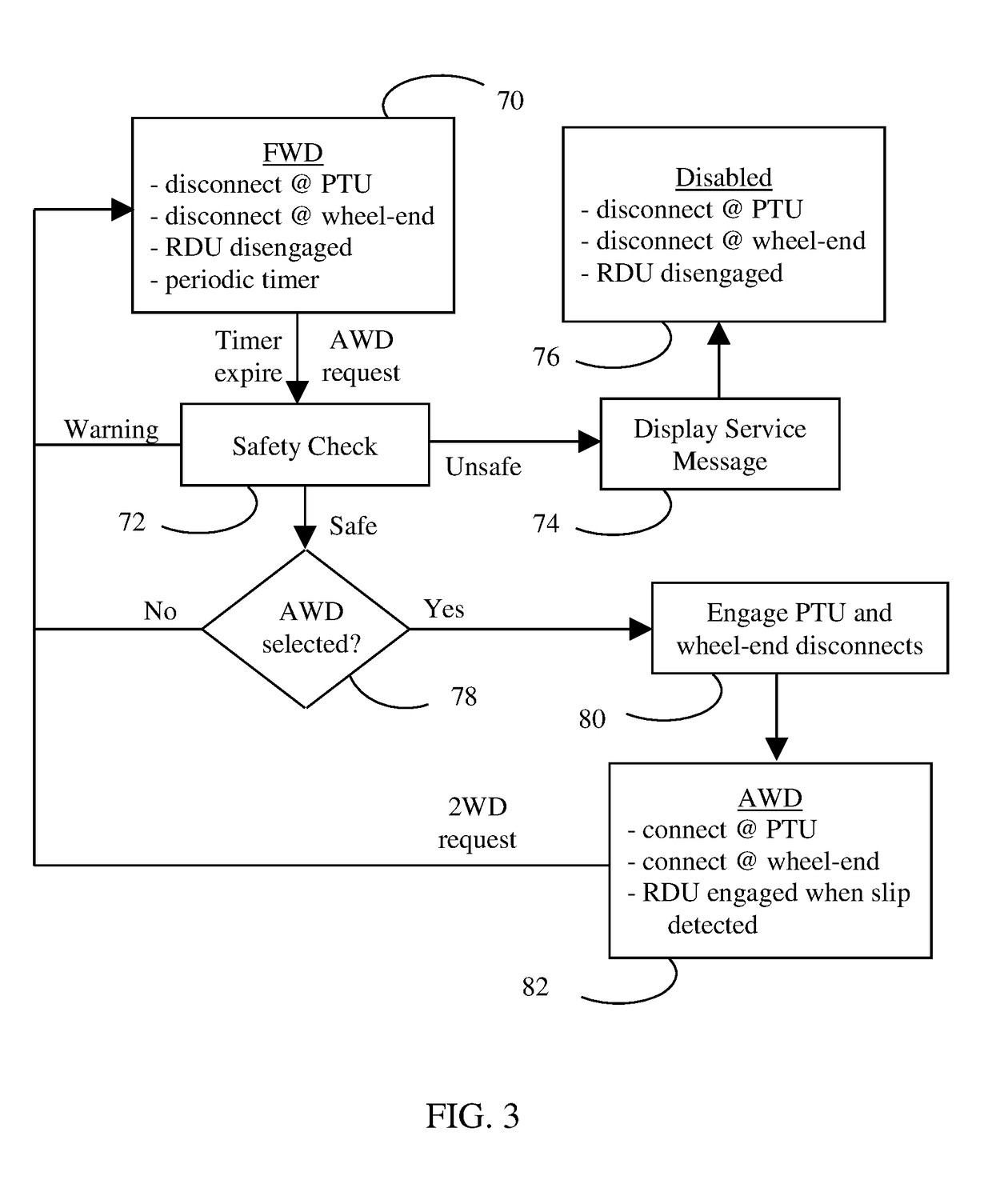
[0005]A vehicle includes a differential, first and second wheels, and a controller. The first wheel is fixedly coupled to a first axle shaft. The second wheel is selectively coupled to a second axle shaft by a clutch. To reduce parasitic losses, the controller disengages the clutch to decouple the second wheel from the second axle shaft while the vehicle is in a front wheel drive mode. In response to a request to enter an all wheel drive mode, the controller engages the clutch if a ratio of a speed of a differential input to a speed of the first axle shaft is less than a first threshold. If the ratio exceeds the first threshold, the controller inhibits engagement of the clutch. The differential may also include a temperature sensor. The controller may inhibit engagement of the clutch if the temperature sensor indicates a temperature exceeding a second threshold. If the temperature then decreases to less than the second threshold, the controller may engage the clutch. If the temperature remains above the second threshold for more than a predetermined duration, the controller may not engage the clutch even when the temperature does decrease to less than the second threshold. The controller may display a message to the driver when it inhibits engagement of the clutch, whether due to the ratio exceeding the first threshold or due to the temperature exceeding the second threshold. The controller may also inhibit engagement of a power-take-off unit.

Problems solved by technology

However, the additional hardware introduces additional parasitic losses which increase fuel consumption even in conditions that do not require the additional capability.

Method used


Image

  • Vehicle with wheel-end disconnect and associated control method
  • Vehicle with wheel-end disconnect and associated control method
  • Vehicle with wheel-end disconnect and associated control method

Examples


Embodiment Construction

[0011]Embodiments of the present disclosure are described herein. It is to be understood, however, that the disclosed embodiments are merely examples and other embodiments can take various and alternative forms. The figures are not necessarily to scale; some features could be exaggerated or minimized to show details of particular components. Therefore, specific structural and functional details disclosed herein are not to be interpreted as limiting, but merely as a representative basis for teaching one skilled in the art to variously employ the present invention. As those of ordinary skill in the art will understand, various features illustrated and described with reference to any one of the figures can be combined with features illustrated in one or more other figures to produce embodiments that are not explicitly illustrated or described. The combinations of features illustrated provide representative embodiments for typical applications. Various combinations and modifications of ...


PUM


Abstract

One vehicle wheel is disconnected from a differential while the vehicle is in a front wheel drive mode. A controller checks for a malfunction of the differential while the vehicle is in the front wheel drive mode and in response to a request to enter an all wheel drive mode. If speeds of the other vehicle wheel and the differential input indicate that the malfunction is present, the all wheel drive mode is disabled and the driver is informed. If fluid temperature indicates a risk of the malfunction, all wheel drive mode is temporarily disabled and the driver is informed. If the temperature condition continues to be present for a predetermined duration, the all wheel drive mode is disabled.

Description

TECHNICAL FIELD[0001]This disclosure relates to the field of vehicle driveline controls. More particularly, the disclosure pertains to a method of controlling an all wheel drive powertrain with a wheel end disconnect.BACKGROUND[0002]Two vehicle powertrain configurations predominate the modern passenger vehicle market, rear wheel drive (RWD) and front wheel drive (FWD). With additional hardware, both of these configurations can be configured to direct power to all four wheels. Because traction at any particular wheel may be limited at certain times, the ability to direct power to all four vehicle improves mobility. However, the additional hardware introduces additional parasitic losses which increase fuel consumption even in conditions that do not require the additional capability.[0003]In a typical RWD configuration, the engine is oriented longitudinally in the vehicle such that the crankshaft axis is aligned with the direction of vehicle movement. A transmission mounted to the engi...

Claims


Application Information

Patent Timeline
Patent Type & Authority Patents(United States)
IPC IPC(8): B60K17/346B60K25/06F16D48/06
CPCF16D48/06B60K17/346B60K25/06F16D2500/50287F16D2500/10425F16D2500/10431B60K17/02B60K17/165B60K17/354B60K2023/0833B60K23/08F16D2500/30404F16D2500/30803F16D2500/3115F16D2500/3168F16D2500/7041F16D2500/7105
Inventor POVIRK, JACOB MARTINSTEINBERG, MIKHAIL
Owner FORD GLOBAL TECH LLC
Why Eureka
Try Eureka