Hydraulically locking limited slip differential

a limited slip differential and hydraulic locking technology, applied in the direction of gearing details, gearing, transportation and packaging, etc., can solve the problems of reduced vehicle fuel efficiency, parasitic losses that grow proportional to the contact diameter of the seal, and reduce vehicle fuel efficiency, so as to reduce parasitic losses and shorten the span

Active Publication Date: 2011-07-19
FCA US
View PDF7 Cites 8 Cited by
  • Summary
  • Abstract
  • Description
  • Claims
  • Application Information

AI Technical Summary

Benefits of technology

[0008]In a preferred embodiment, the present invention provides a pump located externally from the differential housing to thereby provide a more compact LSD with a shorter span between carrier support bearings at the interface between the housing and the carrier than in typical limited slip differentials. The fluid pathway for selective engagement of the clutch may be conveniently positioned beneath one of the carrier support bearings.
[0009]A high-pressure dynamic seal may be required at the interface between the rotating differential carrier and the stationary pump. Typically, high-pressure dynamic seals generate considerable rotating friction which results in parasitic losses and reduced vehicle fuel efficiency. Such parasitic losses grow in proportion to the seal's contact diameter. By moving the pump outside the rotating differential carrier, the carrier-to-pump interface diameter, and, therefore the corresponding seal diameter, may be reduced without increasing the span between the support bearings. So reduced, the seal contact diameter according to the invention will reduce parasitic losses as compared with other limited slip differential designs / configurations.

Problems solved by technology

Typically, high-pressure dynamic seals generate considerable rotating friction which results in parasitic losses and reduced vehicle fuel efficiency.
Such parasitic losses grow in proportion to the seal's contact diameter.

Method used


Image

  • Hydraulically locking limited slip differential
  • Hydraulically locking limited slip differential
  • Hydraulically locking limited slip differential

Examples


Embodiment Construction

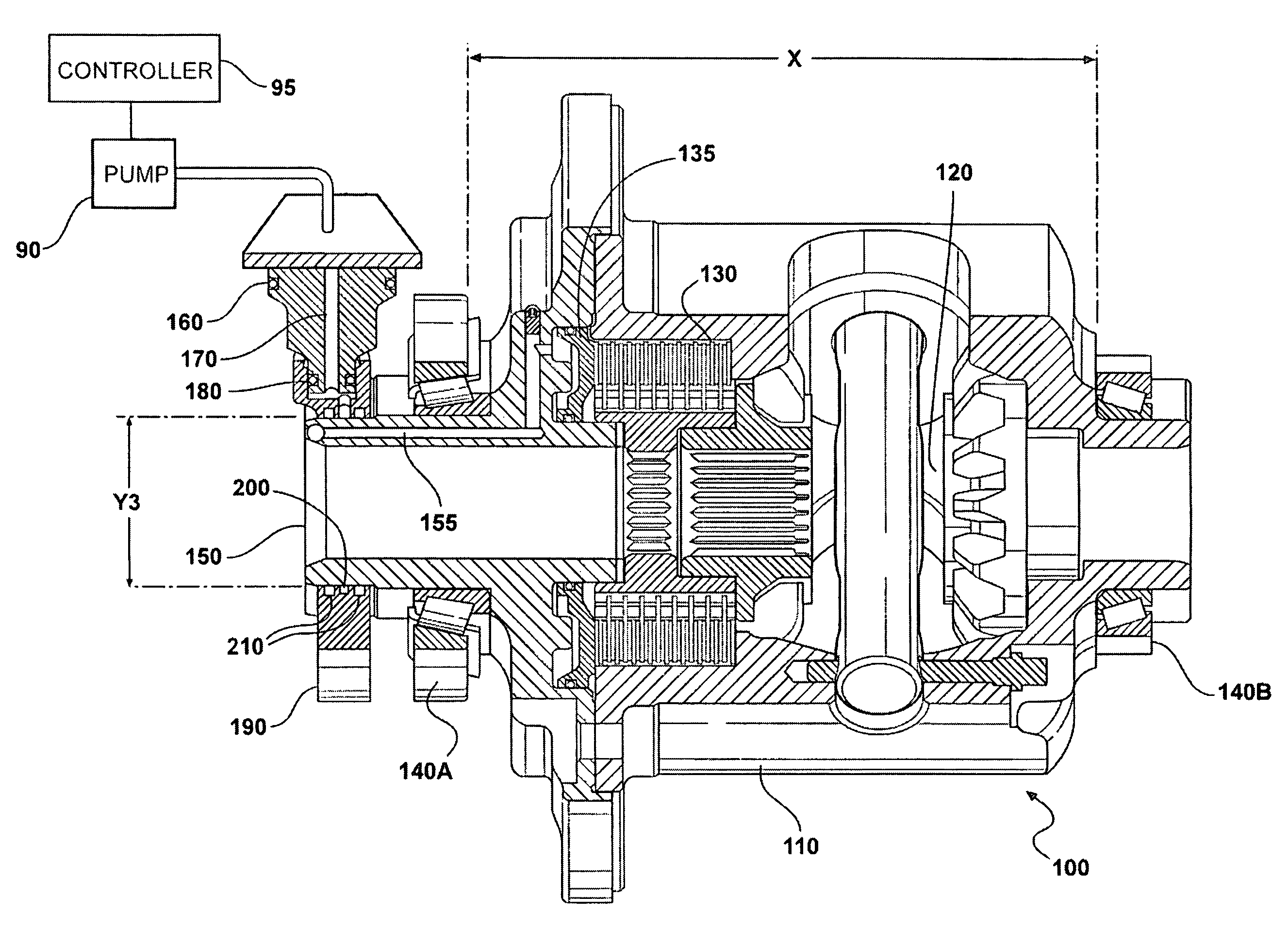
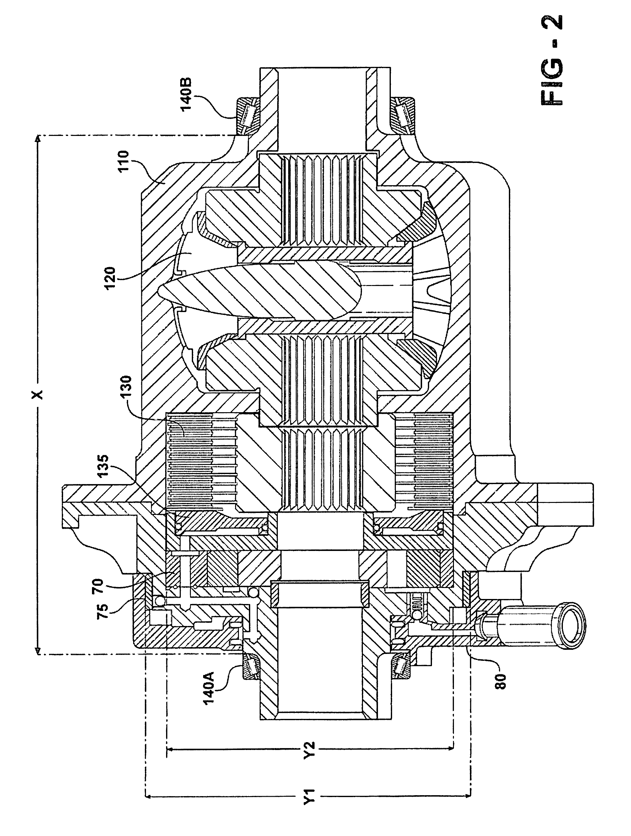
[0016]In general the present invention is directed to a limited slip differential, and, more particularly, to an improved hydraulically locking limited slip differential (LSD) for a motor vehicle. Limited slip differentials are frequently chosen for various vehicle drivelines in place of open type differentials to transfer torque from a slipping drive wheel to one with more grip and thereby improve the vehicle's overall traction capability.

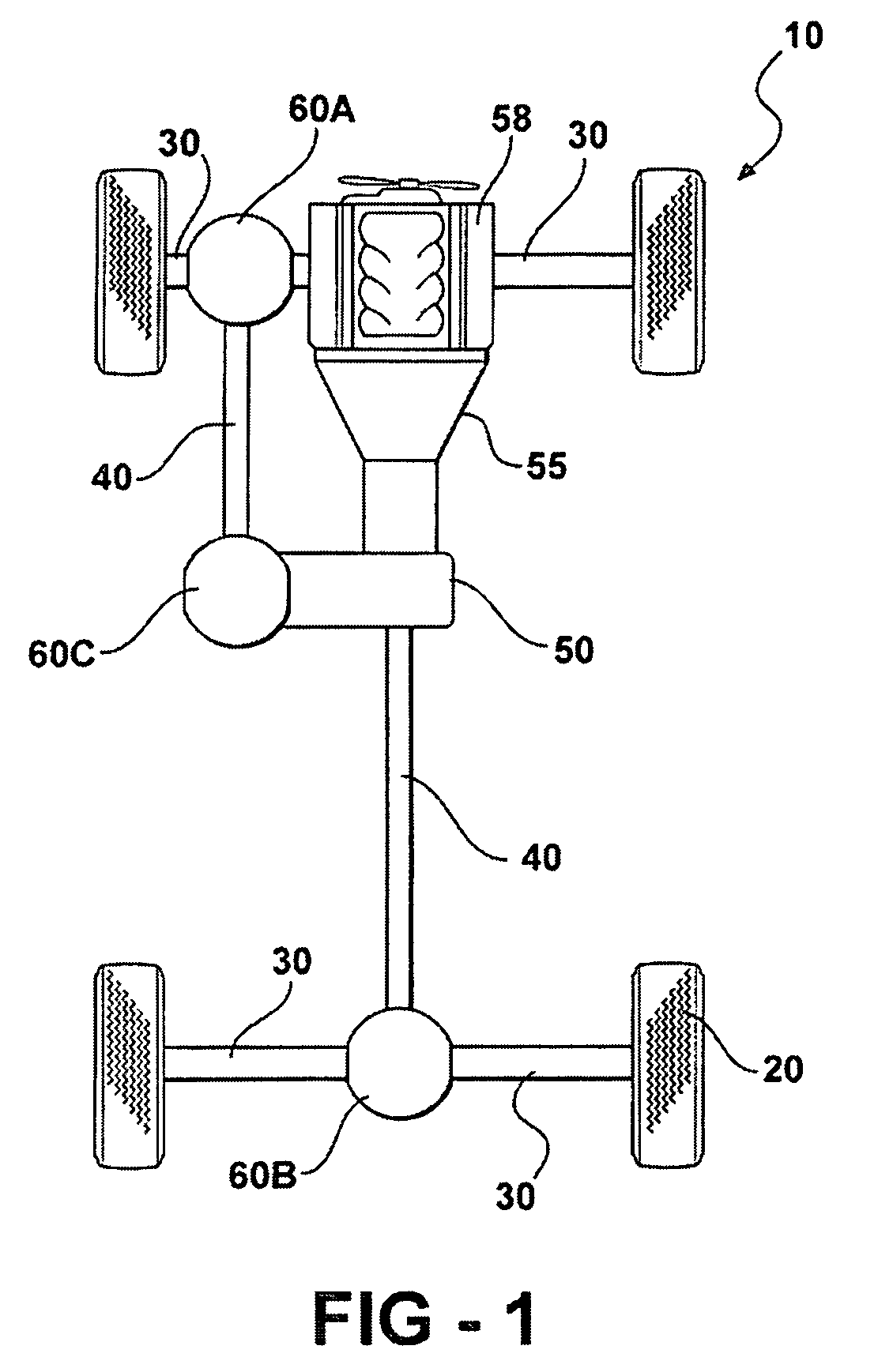
[0017]Each motor vehicle design typically results in unique vehicle traction capabilities, influenced in part by a threshold traction loss at one or more wheels. A threshold traction loss is generally signified by a detectable minimum difference in rotational speed of one of the driven wheels vs. others. The minimum wheel speed difference may be predetermined, i.e. established empirically, during the vehicle development phase under controlled conditions at an instrumented test-facility. A development vehicle may be run on various driving surfaces ...


PUM


Abstract

An improved hydraulically locking limited slip differential assembly for a drivetrain of a motor vehicle having a fluid pump external to a differential carrier and arranged for preventing slip between the wheels by selectively pressurizing a differential clutch internal to the carrier, and a controller arranged for selectively activating the fluid pump.

Description

FIELD OF THE INVENTION[0001]The present invention relates to limited slip differentials, and, more particularly, to an improved hydraulically locking limited slip differential for a motor vehicle.BACKGROUND OF THE INVENTION[0002]Four-wheel and all-wheel drive vehicles are popular for their enhanced capabilities in inclement weather and off-highway conditions as compared with two-wheel drive vehicles. In order to further boost these capabilities, modern four-wheel and all-wheel drive vehicles frequently employ a limited slip differential (LSD) between two respective rear axle-shafts in place of a more common open type differential. Some high performance four-wheel and all-wheel drive vehicles employ a limited slip differential in the front axle, as well, while others go a step further in utilizing a centrally located limited slip differential, i.e. between the axles.[0003]By limiting the velocity difference between a pair of wheels driven by their respective axle half-shafts, an LSD ...

Claims


Application Information

Patent Timeline
Patent Type & Authority Patents(United States)
IPC IPC(8): F16H48/20
CPCF16H48/08F16H48/22F16H48/30F16H48/34F16H48/32F16H48/40F16H2048/204F16H2200/2071
Inventor SCHRAND, EDWARD V.PAJTAS, CHARLES R.
Owner FCA US
Why Eureka
Try Eureka