Torque converter with a lock-up clutch assembly having a floating friction disk

a technology of friction disk and torque converter, which is applied in the direction of rotary clutches, fluid couplings, gearings, etc., can solve the problems of early failure of torque converters, assembly and operational drawbacks, and inconvenient operation, so as to improve the protection of bonded friction materials, prevent exposing friction materials to damage or misalignment, and facilitate construction

Inactive Publication Date: 2008-04-15
BORGWARNER INC
View PDF38 Cites 7 Cited by
  • Summary
  • Abstract
  • Description
  • Claims
  • Application Information

AI Technical Summary

Benefits of technology

[0014]In this manner, the costly and inefficient manufacturing and operational approaches of the prior art with regard to torque converter assemblies having a lock-up clutch are overcome by the present invention that employs a floating friction plate with two friction members. The torque converter of the present invention having a floating friction plate with two separate friction members may be easily constructed in a separate process to protect the bonded friction material and can be installed in the transmission late in the assembly process, which allows much improved protection of the bonded friction material. Further, the friction plate of the present invention is movably supported relative to the annular piston without welding and is floated between the elements of the locking clutch to prevent exposing the friction material to damage or misalignment. In addition, since the floating friction plate of the present invention is not fixed to the annular piston, it is capable of accounting for wear and misalignment within the torque converter. Finally, the floating friction plate of the torque converter of the present invention is a flat annular ring and not a full disc, which has greatly reduced mass to reduce parasitic losses and improve torque converter efficiency.

Problems solved by technology

Directly applying the friction material to the front cover member of the torque converter has been known to present certain assembly and operational drawbacks.
This exposes the delicate frictional material to damage throughout the remainder of the assembly of the transmission that may possibly cause early failure of the torque converter.
Even if the frictional material does not suffer significant damage, small impacts or nicks can change the design performance of the lock-up clutch causing operational inconsistencies.
While torque converters having a lock-up clutch assembly of the type generally known in the related art have preformed reasonably well for their intended purposes, some disadvantages remain.
More specifically, torque converters remain complex devices that take numerous assembly steps and are costly and time consuming to produce.
This again subjects the friction material to possible damage and may cause undetected heat warping of the plate.
Any misalignment will cause improper operation of the lock-up clutch and uneven wear in the friction material since the welded and fixed friction plate will not be able to account for the misalignment.
However, employing a full size friction plate adds additional rotating mass and inertia within the torque converter adding parasitic drain, thereby decreasing torque converter efficiency and adding to operational costs.

Method used


Image

  • Torque converter with a lock-up clutch assembly having a floating friction disk
  • Torque converter with a lock-up clutch assembly having a floating friction disk
  • Torque converter with a lock-up clutch assembly having a floating friction disk

Examples


second embodiment

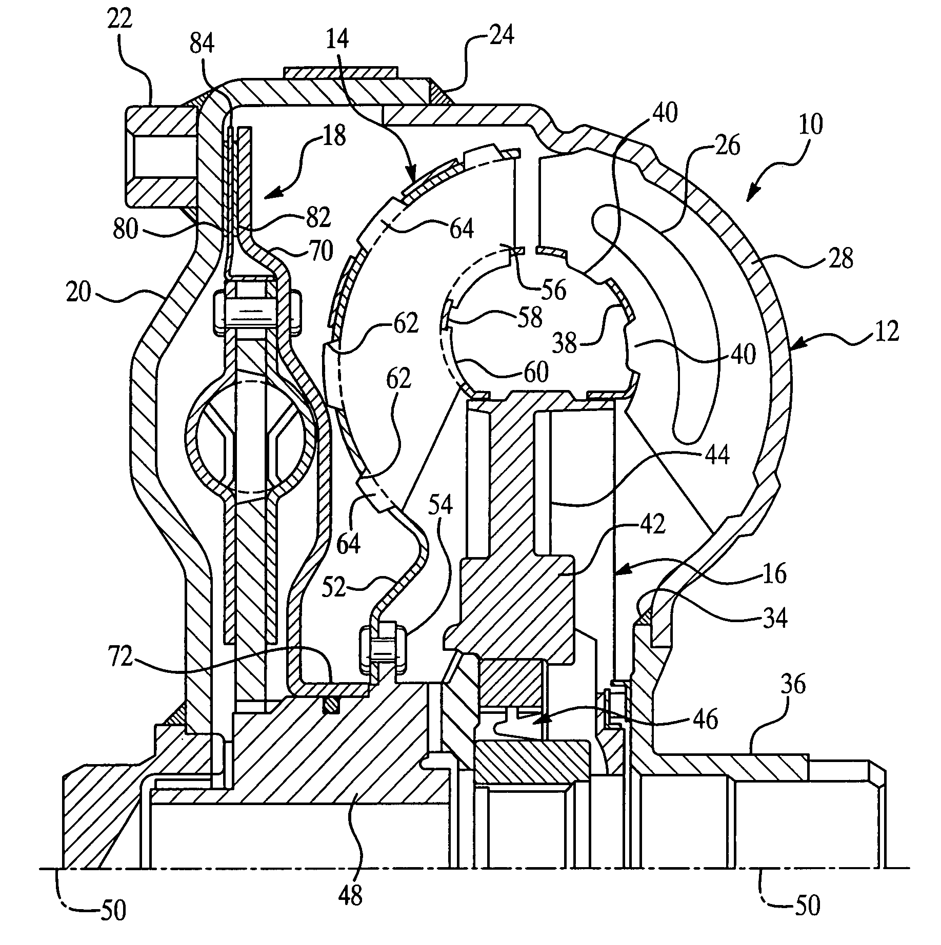
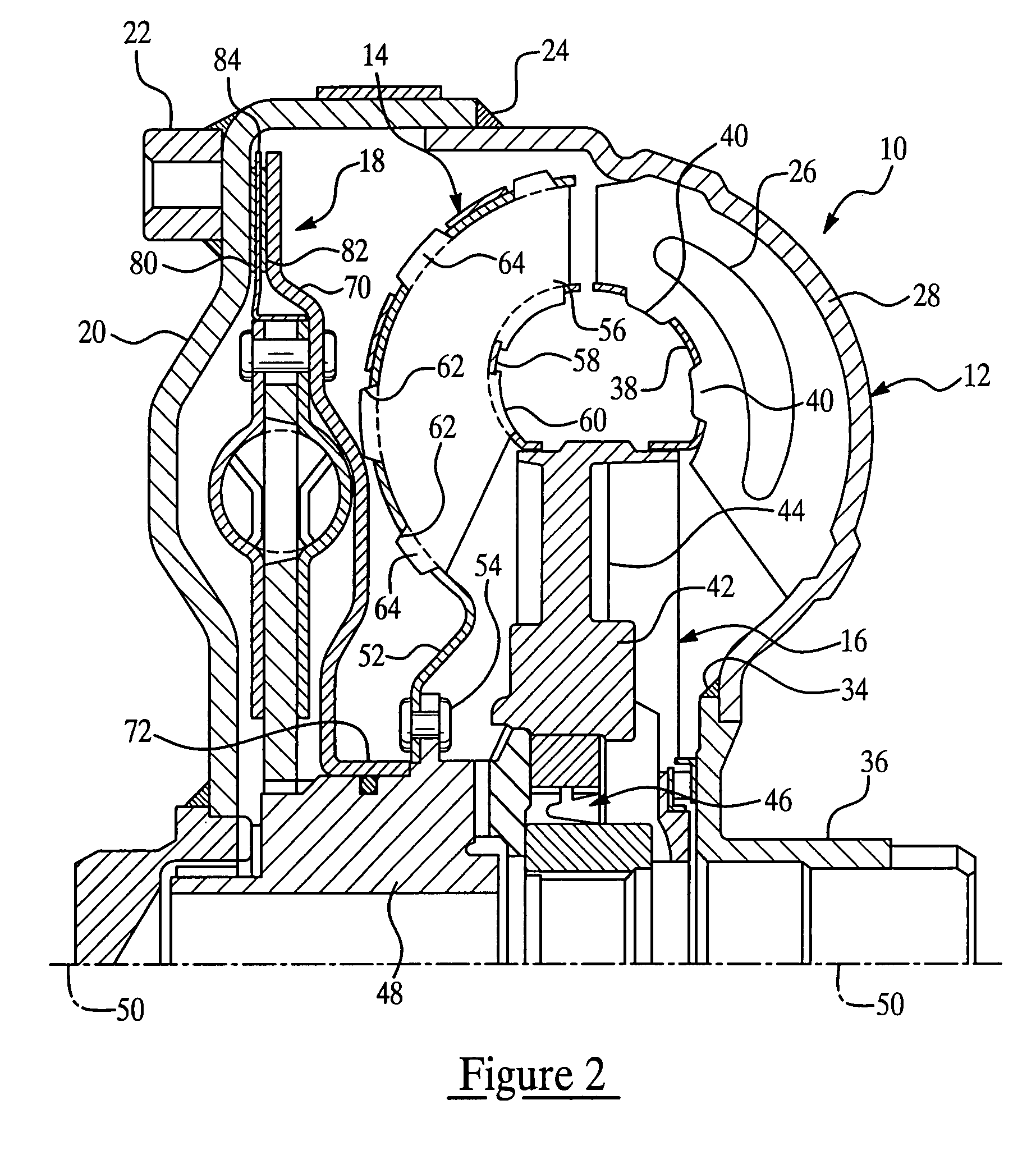
[0041]Referring now to FIG. 5, where like numerals increased by 100 are used to designate structure like that of FIGS. 1 through 3, a second exemplary embodiment of a hydrodynamic torque converter of the present invention is generally indicated at 110. Thus, from a comparison of the figures, those having ordinary skill in the art will appreciate that the hydrodynamic torque converter illustrated in FIG. 5 has all of the same components as that illustrated in FIG. 2, unless specifically described in greater detail below. All of the similar components have similar reference numerals except that those used to designate the components in this second embodiment have been increased by 100. Accordingly, the similar components will not be described in detail here. The torque converter 110 further includes a torsional vibration damper, generally indicated at 176, that is operatively coupled for rotation with the turbine assembly 114. The torsional vibration damper 176 acts to dampen torsiona...

third embodiment

[0051]Referring now to FIGS. 7 through 11, where like numerals incremented by 200 are used to designate like structure, another exemplary embodiment of a hydrodynamic torque converter of the present invention is generally indicated at 210 (FIG. 11). Thus, from the comparison of the figures, those having ordinary skill in the art will appreciate that the hydrodynamic torque converter illustrated in FIG. 11 has all of the same components as that illustrated in FIG. 2 unless specifically described in greater detail below. All of the similar components have similar reference numerals except that those used to designate the components in this third embodiment have been increased by 200. Accordingly, similar components will not be described in detail here. The torque converter 210 further includes a torsional vibration damper, generally indicated at 276, that is operatively coupled for rotation with the turbine assembly 214. The torsional vibration damper 276 acts to dampen torsional vibr...


PUM


Abstract

The torque converter includes a torque input member and an impeller assembly operatively coupled with the torque input member. A turbine assembly is connected with the impeller and a lock-up clutch is interposed between the turbine assembly and the torque input member. The lock-up clutch provides torque translation between the torque input member and the turbine assembly and includes an annular piston mounted to the turbine assembly and a friction plate movably supported relative to the annular piston and operatively disposed between the annular piston and torque input member. A first friction member is operatively disposed between the friction plate and the torque input member, and a second friction member is operatively disposed between the friction plate and the annular piston. Torque is translated from the torque input member through the first friction member, the friction plate, the second friction member, and the annular piston to the turbine assembly.

Description

CROSS-REFERENCE TO RELATED APPLICATION[0001]The present application is a continuation-in-part of U.S. patent application Ser. No. 11 / 058,536, filed Feb. 15, 2005, now abandoned entitled “Torque Converter With A Lock-Up Clutch Assembly Having A Floating Friction Disk.”BACKGROUND OF THE INVENTION[0002]1. Field of the Invention[0003]The present invention relates, generally, to a torque converter having a clutch assembly, and, more specifically, to a torque converter having a lock-up clutch assembly that includes a floating friction disk.[0004]2. Description of the Related Art[0005]In automotive applications, engine torque and speed are translated between a prime mover, such as an internal combustion engine, to one or more wheels through the transmission in accordance with the tractive power demand of the vehicle. Hydrokinetic devices, such as torque converters, are often employed between the internal combustion engine and its associated transmission for transferring kinetic energy ther...

Claims


Application Information

Patent Timeline
Patent Type & Authority Patents(United States)
IPC IPC(8): F16H45/02F16D13/68
CPCF16H45/02F16H2045/0278F16H2045/0289F16D13/64
Inventor KOS, THOMASGRZESIAK, ANTHONYHORNER, ANDREW
Owner BORGWARNER INC
Why Eureka
Try Eureka