Piston pin for heat dissipation

a technology of heat dissipation and pins, which is applied in the direction of trunk pistons, machines/engines, plungers, etc., can solve the problems of forced piston cooling, extreme high temperature, force and inertia,

Inactive Publication Date: 2013-07-11
TENNECO INC
View PDF3 Cites 10 Cited by
  • Summary
  • Abstract
  • Description
  • Claims
  • Application Information

AI Technical Summary

Benefits of technology

[0012]The heat transfer medium trapped inside the sealed cavity of the wrist pin serves as an additional heat sink to help manage the thermal load in a piston assembly and thereby reduce parasitic losses otherwise required to force cooling liquid through the piston assembly. In other words, the sealed cavity in the wrist pin functions as a heat exchanger that absorbs heat directly from the pin boss structure of a piston body to which it is coupled, thus enabling conductive heat migration away from the piston crown.
[0014]The subject invention offers a unique and relatively inexpensive solution to use the wrist pin as an additional heat sink, thereby bringing engine technology one step closer to recovering parasitic losses inherent in prior art systems which require forced piston cooling in order to maintain temperatures below a threshold temperature limit.

Problems solved by technology

Piston assemblies as used in internal combustion engines are subject in use to extremely high temperatures, forces and inertia.
This forced piston cooling represents a parasitic loss.

Method used


Image

  • Piston pin for heat dissipation
  • Piston pin for heat dissipation
  • Piston pin for heat dissipation

Examples


Embodiment Construction

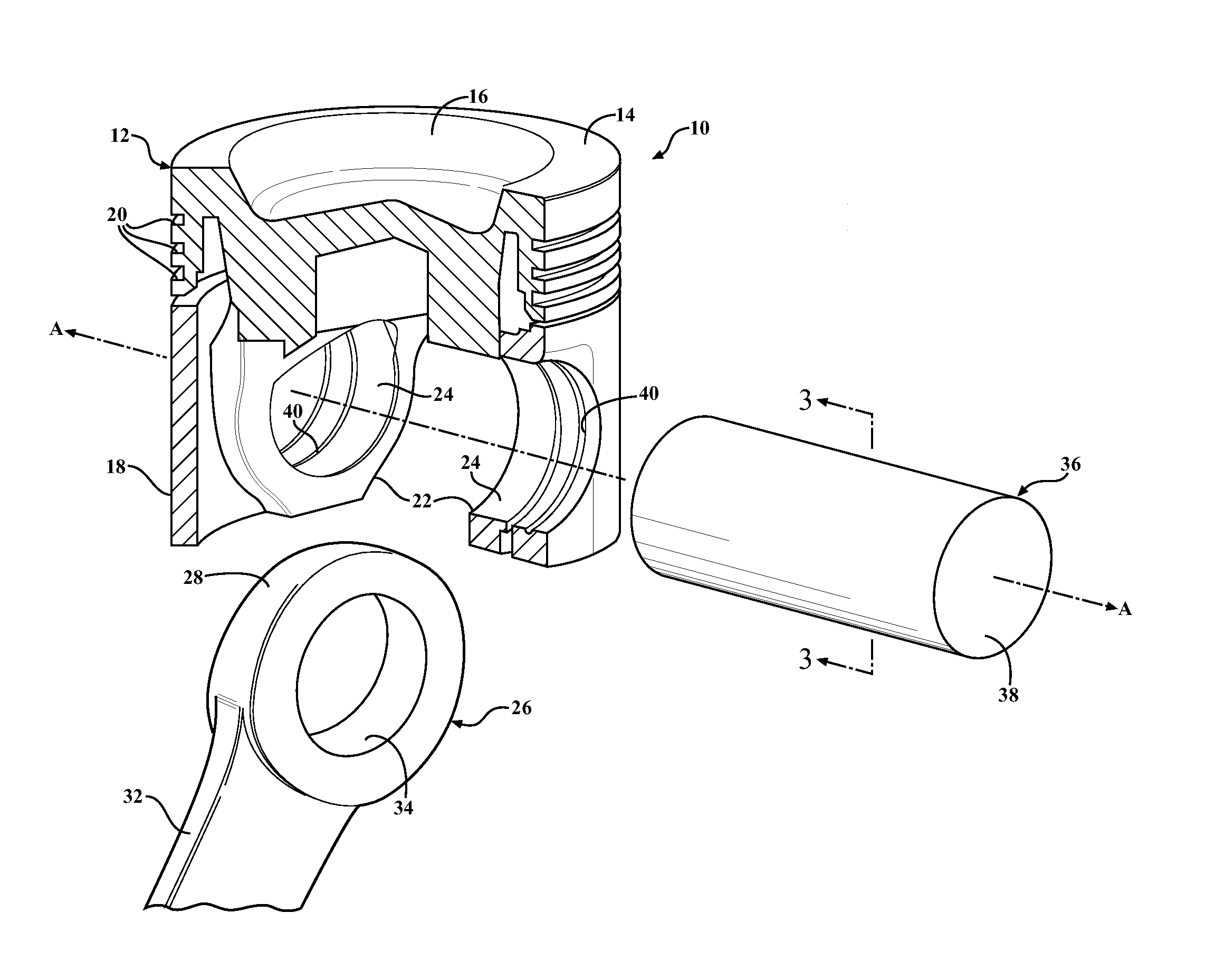
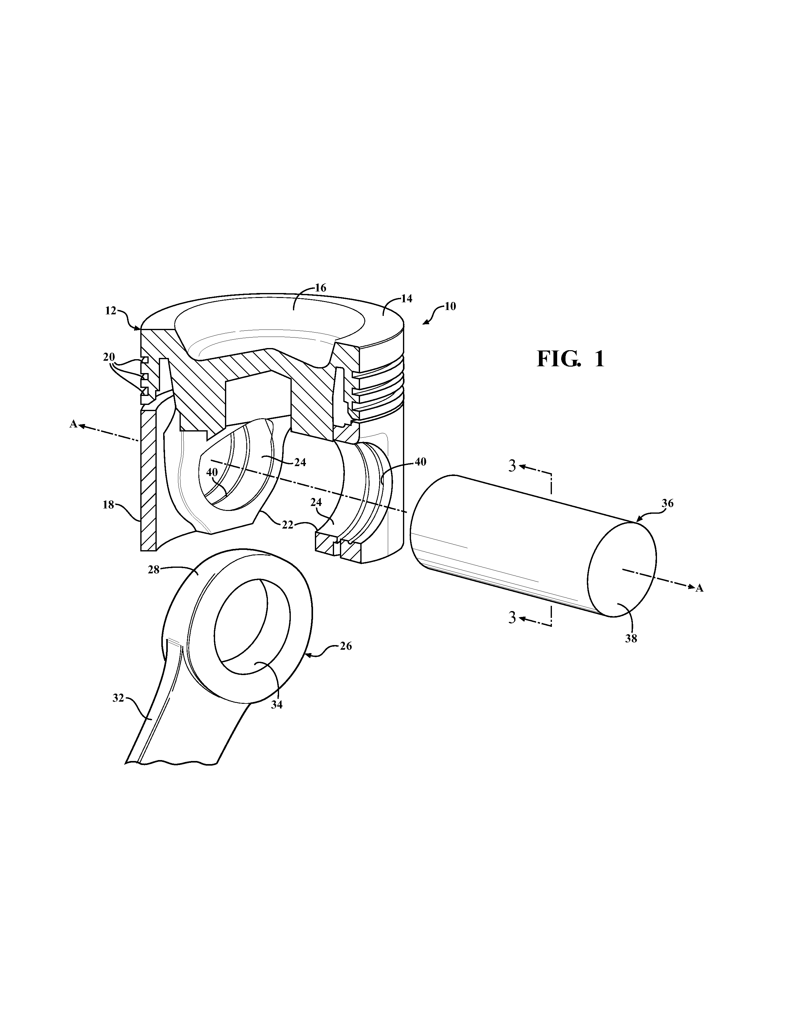
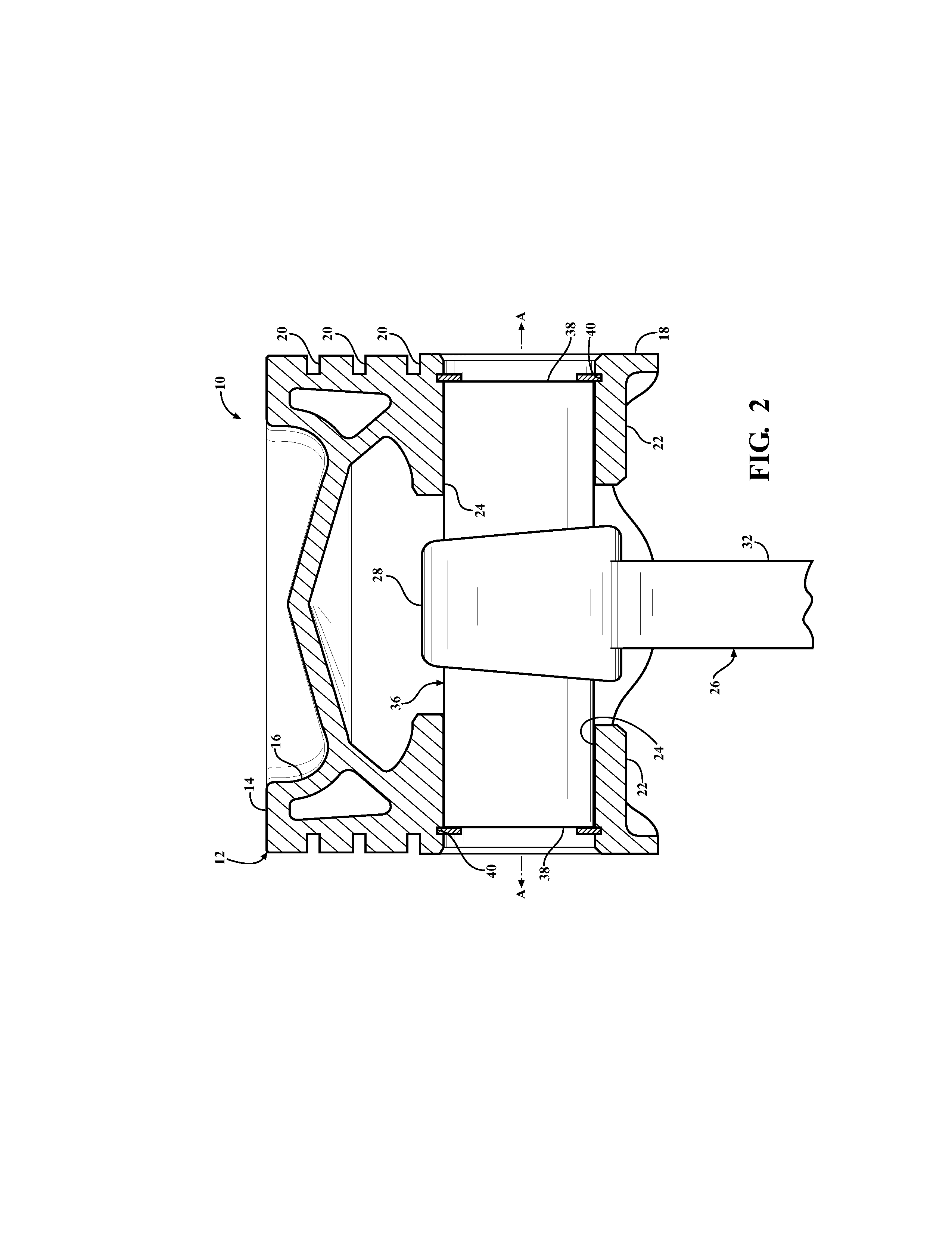
[0022]Referring to the figures wherein like numerals indicate like or corresponding parts throughout the several views, a piston assembly constructed in accordance with preferred embodiments of the invention is generally shown at 10 in FIGS. 1 and 2. The piston assembly 10 includes a piston body, generally indicated at 12. The piston body may be of the single or multi-piece type, and formed with open or closed galleries or other configurations. Those designs shown in FIGS. 1 and 2 are intended for use in diesel engines which is a preferred implementation of this invention, however not the exclusive means by which the novel concepts of this invention may be practiced. As a consequence, the invention herein is applicable to gasoline, natural gas and other types of internal combustion engines in addition to the depicted diesel types. The piston body 12 is formed with a crown 14 at its upper end having, in these examples, a combustion crater or bowl 16. A generally cylindrical skirt 18 ...


PUM


Abstract

A piston assembly including a piston body pivotally connected to a connecting rod by a wrist pin. The wrist pin includes a sealed cavity therein partially filled with a heat transfer medium. The heat transfer medium may be composed of a fusible alloy. The sealed cavity may be comprised of discrete compartments. The wrist pin may be integrated with the connecting rod and share a conjoined sealed cavity therewith so that heat transfer medium can draw heat effectively away from the piston body.

Description

CROSS REFERENCE TO RELATED APPLICATIONS[0001]None.BACKGROUND OF THE INVENTION[0002]1. Field of the Invention[0003]This invention relates to pistons for internal combustion engines, and more particularly to a wrist pin as used in piston assemblies to interconnect the piston body to a connecting rod.[0004]2. Related Art[0005]Piston assemblies as used in internal combustion engines are subject in use to extremely high temperatures, forces and inertia. Optimal operation of such engines requires careful management of the temperature of the components of a piston assembly which are typically manufactured from strong, lightweight metal alloys.[0006]A practice long observed in diesel engine applications is to circulate lubricating oil through passages in the piston assembly to serve as both lubricant for the various joints and as a cooling medium to draw heat away from the piston crown. U.S. Pat. No. 2,742,883 to Smith, issued Apr. 24, 1956, disclose one such piston assembly wherein cooling...

Claims


Application Information

Patent Timeline
Patent Type & Authority Applications(United States)
IPC IPC(8): F16J1/16
CPCF02F3/18F16J7/00F16J1/18F16J1/16
Inventor AZEVEDO, MIGUELZDEBLICK, WILLIAMWANG, KAI
Owner TENNECO INC
Why Eureka
Try Eureka