Weight stand assembly

a technology for weight stands and components, applied in the field of weight stand assemblies, can solve the problems of weight stand assemblies that are prone to retracting and falling off from users, and achieve the effects of increasing the starting point, increasing the amount of weight, and increasing the number of repetitions

Active Publication Date: 2019-03-12
WILKINS ROBERT C
View PDF19 Cites 3 Cited by
  • Summary
  • Abstract
  • Description
  • Claims
  • Application Information

AI Technical Summary

Benefits of technology

[0010]The present invention comprises a weight stand assembly that beneficially allows a user to increase an amount of weight that is being lifted or to increase a number of repetitions of an exercise movement by allowing the user to be able to lift said weights, such as, for example, hand weights, from a beneficially and substantially higher starting point of an exercise lift, and thus, from a position of strength. By not having to begin the exercise movement from a ground surface, or a relatively lower starting point, said user is able to conserve his or her strength and energy for a remainder of the exercise set, and thus potentially perform more repetitions of said exercise movement.
[0011]The weight stand assembly comprises a stand member, having a first and second top member, side insert members, base members, and inner panel members cooperating to form an inner space. First and second top members comprise a substantially indented receiving end that allows for said hand weights to be securely placed in a stable position prior to a user performing an exercise movement. When said hand weights are securely positioned within receiving ends of first and second top members, stand member is thus situated in a relatively stable and balanced upright position. Further, first top member comprises a substantially vertical indentation for use in allowing a user's arm to fit within inner space of stand member, and thus, properly grasp said resting hand weights, without contacting any other component of said stand member. As a result, said user is able to freely grasp said hand weights prior to performing an exercise movement without being hindered by said weight stand assembly. Additionally, stand member comprises a plurality of side insert members that can be attachably connected and added to weight stand assembly, as needed. As a result, side insert members avow a user to be able to adjust a desired height of said apparatus, thereby being able to tailor said weight stand assembly to each particular user.
[0012]The present invention represents an improvement over a conventional exercise device because it allows for a user to be able to start an exercise movement from a position of strength, while then providing a mechanism for moving out of a user's way once he or she begins the exercise repetitions. For example, the weight stand assembly comprises a lever that is positioned along a base end of said stand member. Said lever comprises a load that allows said stand member to retract and fall away from a user in a relatively backward direction towards a ground surface once said hand weights have been lifted from stand member.
[0013]As a result, once the weights have been lifted, the center of mass of said weight stand assembly shifts due to said lever having a desired load, thereby causing weight stand assembly to retract and fall away from said user. Thus, said retractable weight stand assembly is designed and intended to fall away from a user in a relatively backwards direction when said user lifts said weights from said stand member in order to perform an exercise set, thereby allowing a user to perform multiple exercise repetitions in said exercise set without user potentially making direct contact with said weight stand assembly during a course of an exercise movement.

Problems solved by technology

As a result, once the weights have been lifted, the center of mass of said weight stand assembly shifts due to said lever having a desired load, thereby causing weight stand assembly to retract and fall away from said user.

Method used


Image

  • Weight stand assembly
  • Weight stand assembly
  • Weight stand assembly

Examples


Embodiment Construction

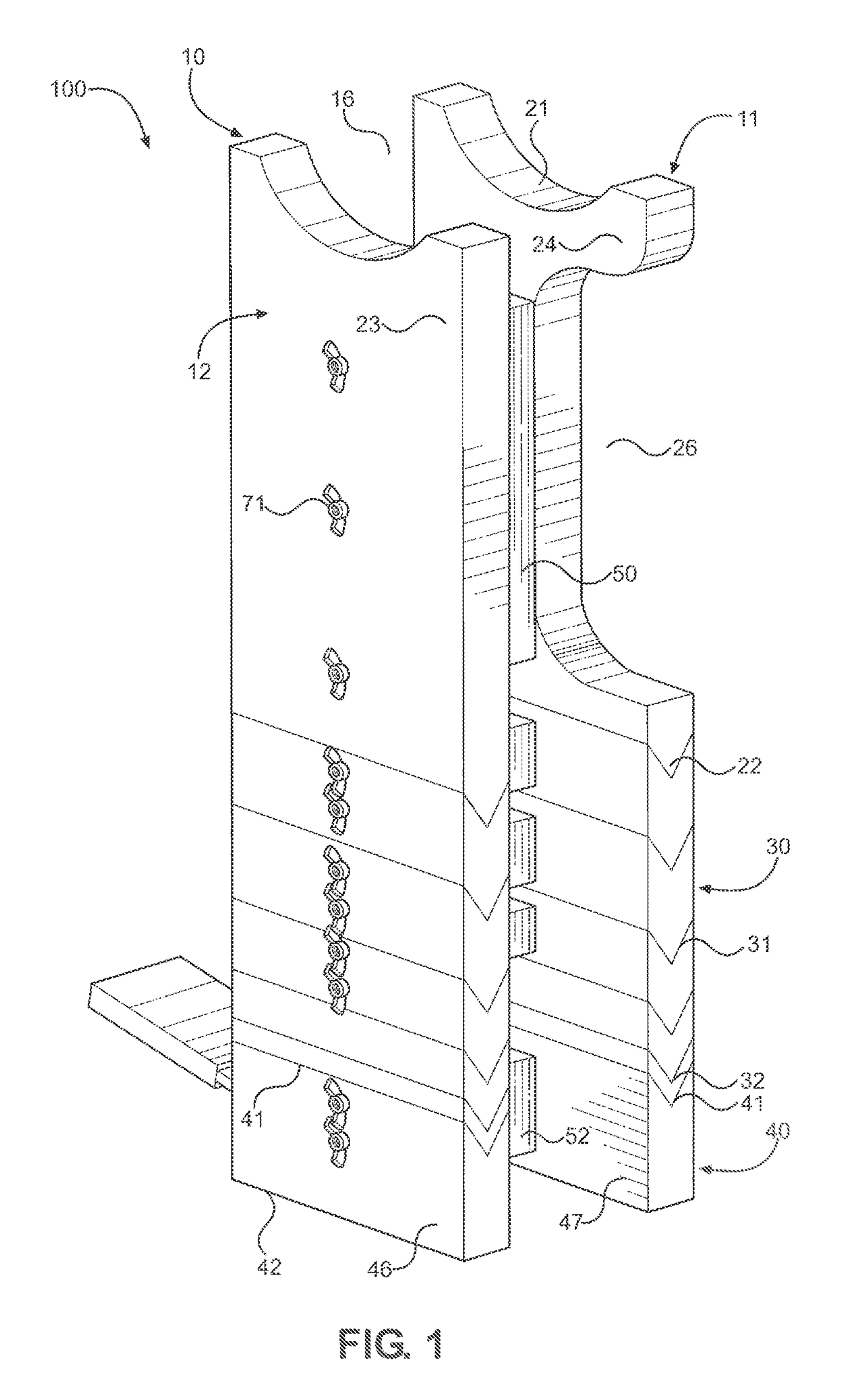
[0022]Referring to the drawings, FIG. 1 depicts a perspective view of a weight stand assembly 100 of the present invention generally comprising at least one stand member 10. Stand member 10, or body member, comprises a substantially rigid frame that can be manufactured from a solid structural material, such as, for example, plastic, composite, wood or a simulated wood product, or any other substantially solid material exhibiting like characteristics. Moreover, weight stand assembly 100 can be assembled in a variety of different dimensions, thereby allowing a user to be able to custom fit weight stand assembly 100 in order to meet any desired height requirements.

[0023]In a preferred embodiment, stand member 10 generally comprises a plurality of panels that are braced and connected via a plurality of bolts 71, mechanical fasteners, adhesive, or any other similar attachment means. Still referring to FIG. 1, stand member 10 generally comprises a first 11 and a second 12 substantially pl...


PUM


Abstract

A weight stand assembly for use in assisting a user prior to performing an exercise movement or repetition by way of holding exercise weights used by the user in a relatively stable and proper starting position for the user. More particularly, the weight stand assembly is retractable in that it pivotally falls in a relatively backwards direction away from the user and towards a ground surface after the exercise weights have been lifted by the user, thereby preventing injury and thus enhancing performance of the user by allowing the user to complete a full set of exercise repetitions without being inhibited by a placement and location of the weight stand assembly.

Description

CROSS REFERENCES TO RELATED APPLICATION[0001]Priority of U.S. Provisional Patent Application Ser. No. 62 / 216,732, filed Sep. 10, 2015, incorporated herein by reference, is hereby claimed.STATEMENTS AS TO THE RIGHTS TO THE INVENTION MADE UNDER FEDERALLY SPONSORED RESEARCH AND DEVELOPMENT[0002]NoneBACKGROUND OF THE INVENTION[0003]Field of the Invention[0004]The present invention pertains to a weight stand assembly for use in assisting a user prior to performing an exercise movement or repetition by holding said user's exercise equipment (such as, for example, free weights, hand weights, dumbbells, or bar bells) in a relatively stable and proper starting position for said user. More particularly, the present invention pertains to a retractable weight stand assembly that pivotally falls (typically in a relatively backwards direction away from said user and generally towards a ground or other underlying surface) after said exercise equipment, or weights, have been lifted by said user, th...

Claims


Application Information

Patent Timeline
Patent Type & Authority Patents(United States)
IPC IPC(8): A63B21/062A63B21/072A63B21/078E04B1/26
CPCA63B21/078A63B21/0626A63B21/0726E04B2001/2616A63B2225/093
Inventor WILKINS, ROBERT C.
Owner WILKINS ROBERT C
Why Eureka
Try Eureka