Water-cooling radiator of computer host CPU
A water-cooled radiator, computer host technology, applied in the direction of instruments, electrical digital data processing, digital data processing components, etc., can solve the problem of low heat exchange efficiency, improve the flow state, prolong the heat exchange time, and increase the contact. effect of time
- Summary
- Abstract
- Description
- Claims
- Application Information
AI Technical Summary
Problems solved by technology
Method used
Image
Examples
Embodiment 1
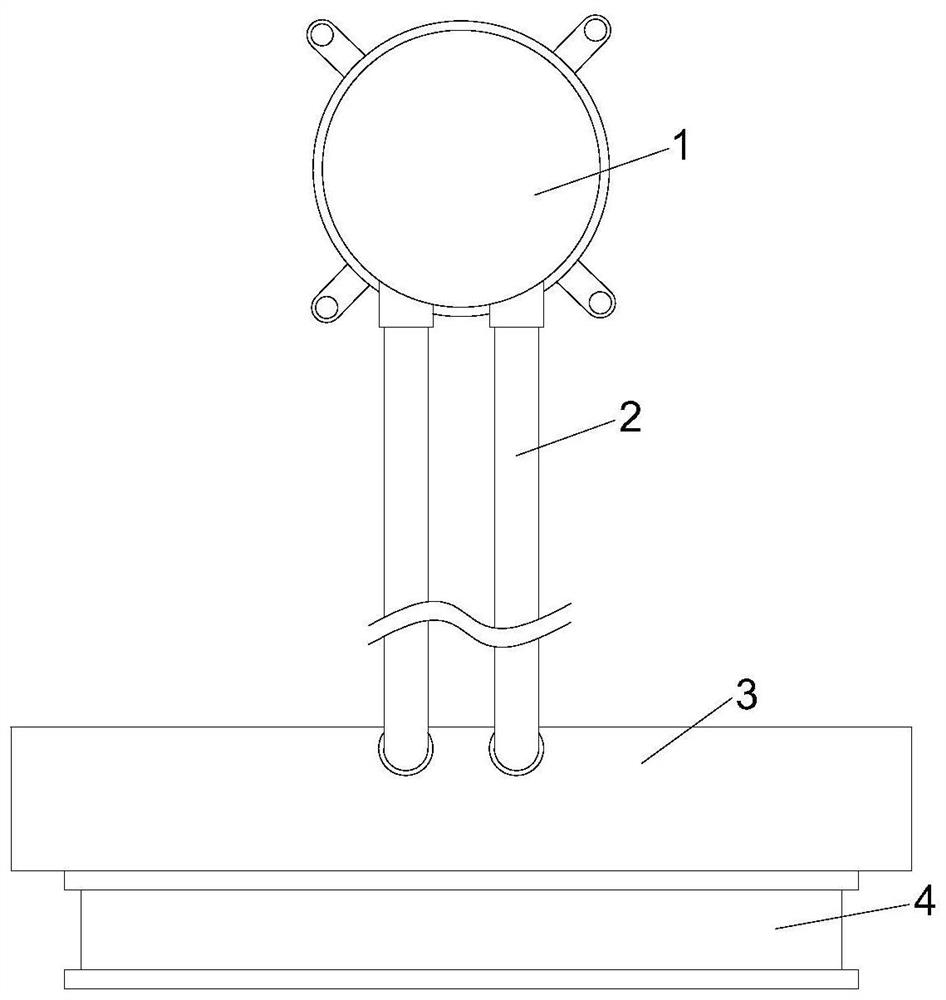
[0032] like Figure 1-2 As shown, the present invention provides a water-cooled radiator for a computer mainframe CPU, including a CPU water-cooling head 1, the water pipe joint of the CPU water-cooling head 1 is connected to a heat exchange mechanism 3 through a water-cooling liquid pipe 2, and a fan is installed on the heat exchange mechanism 3 Group 4, the heat exchange mechanism 3 includes a main casing 31, the inner wall of the main casing 31 is provided with a closed frame 32, and the outer side of the closed frame 32 is sealed and fixed with a heat-conducting partition 35, and the heat-conducting partition 35 is located in the main casing 31 is provided with a flow guiding mechanism 33 and a heat-absorbing fin group 34 on one side inside, the heat-absorbing fin group 34 is arranged in the flow guiding mechanism 33, and the side surface of the heat-conducting partition 35 away from the flow-guiding mechanism 33 is provided with a cooling fin Sheet 36 and fan base 37, scr...
Embodiment 2
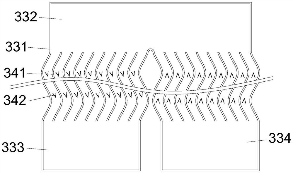
[0035] like image 3 As shown, on the basis of Embodiment 1, the present invention provides a technical solution: the diversion mechanism 33 includes a diversion box 331, and the diversion box 331 is a U-shaped copper tube with a rectangular cross section, and the diversion box The body 331 and the heat-conducting partition 35 are sealed and welded, and a sealing coating is applied between the diversion box 331 and the main shell 31. The bend of the diversion box 331 is the tail end channel 332, and the diversion box Two ends of the body 331 are an inlet nozzle 333 and an outlet nozzle 334 respectively.
[0036] In this embodiment, the water-cooling liquid enters the diversion box 331 through the inlet nozzle 333, then passes through the tail end channel 332 and then is output from the outlet nozzle 334. The U-shaped design integrates the circulation pipe of the water-cooling liquid, increasing the water cooling The distance the liquid travels during heat exchange.
Embodiment 3
[0038] like Figure 4-5 As shown, on the basis of Embodiment 2, the present invention provides a technical solution: the diversion structure 341 includes curved fins 3411, the curved fins 3411 are curved, and their height is equal to the thickness of the diversion box 331 , its length is less than the length of the straight pipe section of the diversion box 331, the side wall of the diversion box 331 corresponding to the curved fins 3411 is curved, and spoiler scales 3412 are arranged on both sides of the curved fins 3411, the spoilers The flow scale 3412 includes the scale body a1, and the scale body a1 is provided with three diversion holes a2, and the outside of the tip of the scale body a1 is provided with a diversion scale a3, and the three diversion holes a2 are arranged in the shape of a character on the diversion scale a3 away from One side of the tip of the scale body a1.
[0039] In this embodiment, the curved fins 3411 designed in a curved shape can divert the wate...
PUM
 Abstract
Description
Claims
Application Information
 - R&D
- Intellectual Property
- Life Sciences
- Materials
- Tech Scout
- Unparalleled Data Quality
- Higher Quality Content
- 60% Fewer Hallucinations
Browse by: Latest US Patents, China's latest patents, Technical Efficacy Thesaurus, Application Domain, Technology Topic, Popular Technical Reports.
© 2025 PatSnap. All rights reserved.Legal|Privacy policy|Modern Slavery Act Transparency Statement|Sitemap|About US| Contact US: help@patsnap.com


