High-performance catalyst support

a catalyst and high-performance technology, applied in the field of catalytic fuel reforming, can solve the problems of limiting heat transfer from the tube wall into the packed bed, difficult to transfer heat through the packed media, and only marginal packing near the center, so as to prolong the useful life of the catalytic reformer, reduce or eliminate, and facilitate the flow of hea

Active Publication Date: 2006-01-26
JOHNSON MATTHEY PLC
View PDF37 Cites 54 Cited by
  • Summary
  • Abstract
  • Description
  • Claims
  • Application Information

AI Technical Summary

Benefits of technology

[0013] The invention has a further object of providing a high-temperature catalyst support which facilitates the flow of heat from outside the support to the interior of the support.
[0014] The invention has the further object of reducing or eliminating the problem associated with thermal mismatch between a metal pipe and a ceramic catalyst material.
[0015] The invention has the further object of prolonging the useful life of a catalytic reformer or heat exchanger.
[0016] The invention has the further object of improving the efficiency, and / or reducing the cost, of a steam reforming process.
[0017] The invention has the further object of providing an improved means of making hydrogen for a fuel cell, or other hydrogen-using process, by providing an improved catalyst support for use in a steam reforming process.

Problems solved by technology

First, heat transfer from the tube wall into the packed bed is a limiting factor.
While heat can be quickly transferred, by conduction, through the metal tube wall, it is difficult to transfer heat through the packed media so as to reach the media near the center of the tube.
Consequently, most of the system performance comes from the packing near the walls, and the packing near the center is only marginally effective.
Secondly, the thermal expansion mismatch between metal and ceramic limits the durability of the system.
Changing the packed media is an expensive process, and requires that the reactor be shut down for a period of time.

Method used


Image

  • High-performance catalyst support
  • High-performance catalyst support
  • High-performance catalyst support

Examples


Embodiment Construction

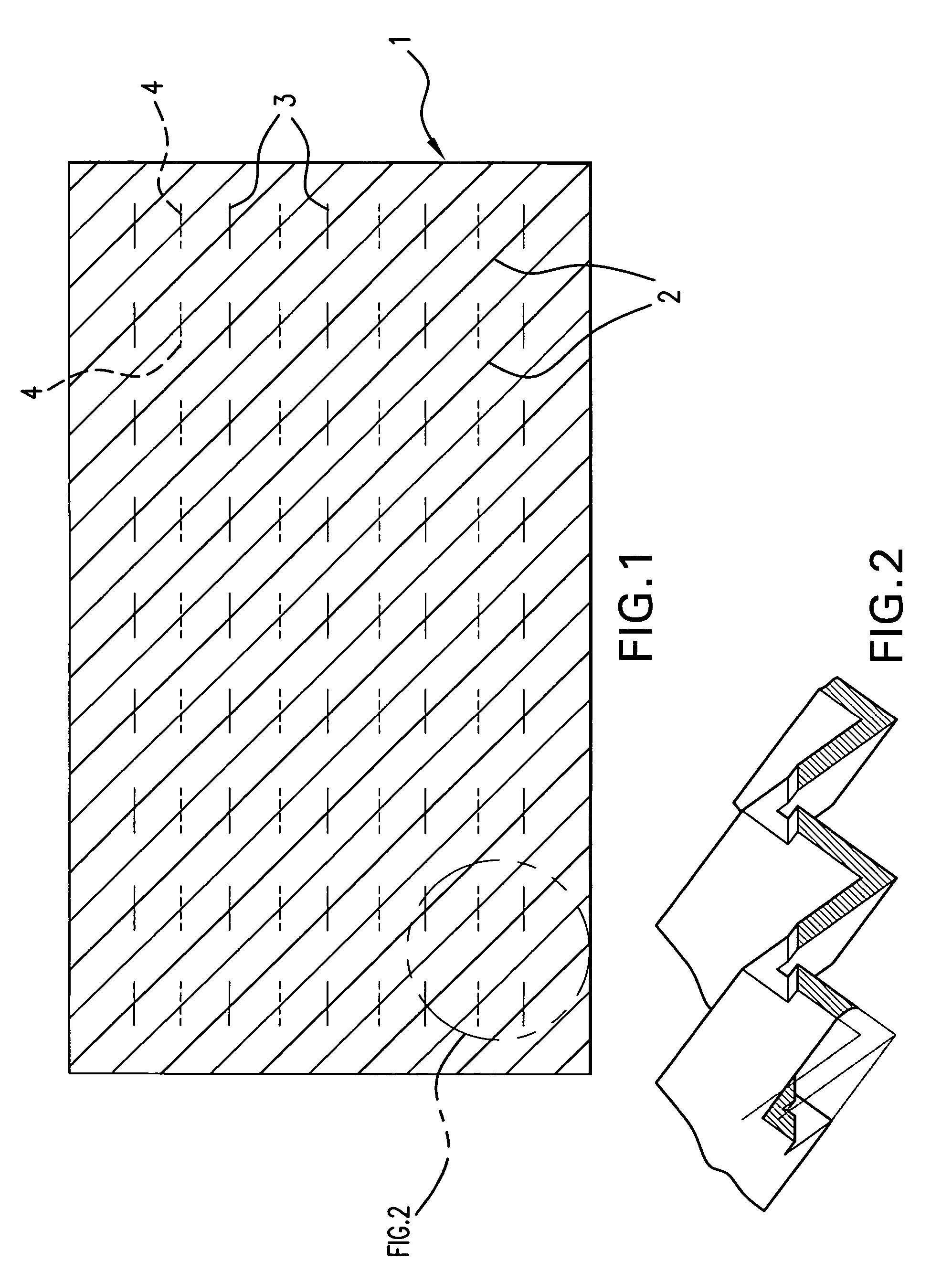
[0025] The catalyst support of the present invention is assembled from a plurality of corrugated strips of metal foil, a typical strip 1 being illustrated in FIG. 1. The foil has corrugations 2 which are oblique with respect to the longitudinal and transverse edges of the strip. In a preferred embodiment, wherein the pieces of foil are generally square or rectangular, the corrugations may form an angle of approximately 45 degrees with respect to the edges. But the exact angle is not critical, as virtually any oblique orientation of the corrugations can be used in the present invention.

[0026] The strip also has a plurality of slits 3 formed in the top side of the foil, i.e. the side facing the reader, and a plurality of slits 4 formed in the bottom side, the slits 3 and 4 alternating with each other as shown. The slits are cut into the apex or crown of the corrugations, and preferably extend to a depth of approximately one-third of the total height of the corrugation. For example, i...


PUM

PropertyMeasurementUnit
diameteraaaaaaaaaa
temperatureaaaaaaaaaa
angleaaaaaaaaaa

Abstract

A catalyst support is formed of a monolith having corrugated metal leaves. The corrugations of each leaf are oblique relative to the edges of the leaf. Each leaf extends from an interior region to an exterior region, and has corrugations that are non-parallel to the corrugations in an adjacent leaf. Each leaf also includes slits, and is coated with a suitable catalyst. A set of monoliths, made as described above, are stacked within a cylindrical pipe. The corrugations define gas flow channels, which enable heat applied to the exterior of the pipe to travel to the center of the monolith, and back to the outside. The support of the present invention thus facilitates heat transfer to essentially all regions of the monolith. The invention also inherently overcomes the problem associated with thermal mismatch between the metal pipe and a ceramic catalyst material.

Description

BACKGROUND OF THE INVENTION [0001] This invention relates to the field of catalytic fuel reforming, and provides a catalyst support capable of operation at high temperatures, such as are encountered in a steam reforming process. [0002] A fuel cell produces an electric current using hydrogen as a starting material. The hydrogen required by a fuel cell is typically made by a steam reforming process, in which a hydrocarbon fuel is reacted with water, the water being in the form of steam. The steam reforming reaction is endothermic, and therefore requires a source of heat. [0003] Other industrial processes, such as oil and gas refining, ammonia and fertilizer production, hydrogenation of oils and chemicals, and iron ore reduction, also use hydrogen as a beginning or intermediate part of the process. Most of these processes also use steam reforming of hydrocarbon fuel, usually natural gas, to make the hydrogen. [0004] In the prior art, it has been known to use shaped ceramic catalysts in...

Claims


Application Information

Patent Timeline
Patent Type & Authority Applications(United States)
IPC IPC(8): B01J20/28
CPCB01J19/2485C01B2203/1023B01J19/30B01J19/32B01J35/04B01J37/0225B01J2219/2455B01J2219/2459B01J2219/246B01J2219/2461B01J2219/2479B01J2219/2485B01J2219/2493B01J2219/30284B01J2219/30288B01J2219/30292B01J2219/30408B01J2219/30475B01J2219/3085B01J2219/3181B01J2219/3221B01J2219/32244B01J2219/32272B01J2219/32408B01J2219/32466B01J2219/32475B01J2219/3281C01B3/38C01B3/40C01B2203/0233C01B2203/1005B01J19/249Y02P20/52
Inventor WHITTENBERGER, WILLIAM A.
Owner JOHNSON MATTHEY PLC
Why Eureka
Try Eureka