
Controlling multi-pass rendering sequences in a cache tiling architecture

a multi-pass rendering and cache technology, applied in the field of computer processing, can solve the problems of unnecessarily consuming memory bandwidth and power, and parallel processing systems cannot effectively execute “multi-pass” rendering sequences across multiple render targets, so as to optimize arbitrarily complex multi-pass rendering sequences, optimize data flow, and reduce memory bandwidth consumption

Active Publication Date: 2020-01-14
NVIDIA CORP
View PDF208 Cites 53 Cited by
  • Summary
  • Abstract
  • Description
  • Claims
  • Application Information

AI Technical Summary

Benefits of technology

This approach optimizes memory bandwidth consumption and improves cache memory utilization for complex multi-pass rendering sequences by dynamically processing dependencies, ensuring data is retained in cache memory where needed and invalidating unnecessary data, thereby reducing power consumption.

Problems solved by technology

While parallel processing systems that implement such a “single-pass” tiling technique may optimally execute single-pass rendering tasks, such parallel processing systems do not effectively execute “multi-pass” rendering sequences across multiple render targets.
One drawback to implementing such pre-defined sets of render target operations is that software applications often create multi-pass rendering sequences during execution to implement a variety of rendering tasks, such as texture mapping tasks.
Because such multi-pass sequences are unknown prior to execution, properly capturing such a sequence with a pre-defined set of render target operations is quite difficult, and attempts to do so usually results in errors.
Notably, if the pre-defined set of render target operations does not properly reflect the data dependencies, then the parallel processing system typically resorts to writing intermediate data out to the frame buffer after the first pass, unnecessarily consuming memory bandwidth and power.

Method used


Image

  • Controlling multi-pass rendering sequences in a cache tiling architecture
  • Controlling multi-pass rendering sequences in a cache tiling architecture
  • Controlling multi-pass rendering sequences in a cache tiling architecture

Examples


Embodiment Construction

[0025]In the following description, numerous specific details are set forth to provide a more thorough understanding of the present invention. However, it will be apparent to one of skill in the art that the present invention may be practiced without one or more of these specific details.

System Overview

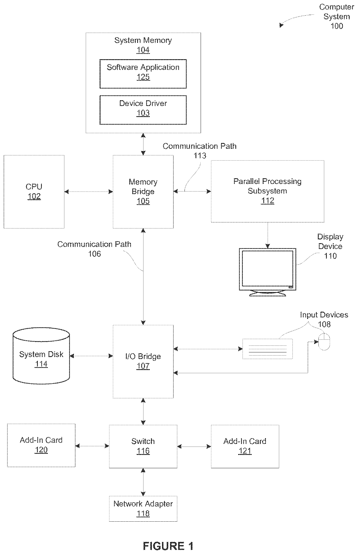
[0026]FIG. 1 is a block diagram illustrating a computer system 100 configured to implement one or more aspects of the present invention. As shown, computer system 100 includes, without limitation, a central processing unit (CPU) 102 and a system memory 104 coupled to a parallel processing subsystem 112 via a memory bridge 105 and a communication path 113. Memory bridge 105 is further coupled to an I / O (input / output) bridge 107 via a communication path 106, and I / O bridge 107 is, in turn, coupled to a switch 116.

[0027]In operation, I / O bridge 107 is configured to receive user input information from input devices 108, such as a keyboard or a mouse, and forward the input information to C...


PUM


Abstract

In one embodiment of the present invention a driver configures a graphics pipeline implemented in a cache tiling architecture to perform dynamically-defined multi-pass rendering sequences. In operation, based on sequence-specific configuration data, the driver determines an optimized tile size and, for each pixel in each pass, the set of pixels in each previous pass that influence the processing of the pixel. The driver then configures the graphics pipeline to perform per-tile rendering operations in a region that is translated by a pass-specific offset backward—vertically and / or horizontally—along a tiled caching traversal line. Notably, the offset ensures that the required pixel data from previous passes is available. The driver further configures the graphics pipeline to store the rendered data in cache lines. Advantageously, the disclosed approach exploits the efficiencies inherent in cache tiling architecture while honoring highly configurable data dependencies between passes in multi-pass rendering sequences.

Description

BACKGROUND OF THE INVENTION[0001]Field of the Invention[0002]Embodiments of the present invention relate generally computer processing and, more specifically, to controlling multi-pass rendering sequences in a cache tiling architecture.[0003]Description of the Related Art[0004]Some parallel processing systems implement a tiling architecture in which a render target is divided into cache tiles. Work received by such a parallel processing subsystem is rearranged such that the work is processed in cache tile order, as opposed to primitive order. More specifically, work associated with a first cache tile is processed first, then work associated with a second cache tile is processed, then work associated with a third cache tile, and so forth. In some implementations, data associated with cache tiles is maintained in an on-chip cache memory while the cache tiles are being processed, which reduces the amount of traffic between the on-chip cache memory and off-chip frame buffer. Such an app...

Claims


Application Information

Patent Timeline
Patent Type & Authority Patents(United States)
IPC IPC(8): G06T1/20G09G5/36G09G5/14G09G5/02G09G5/39G06T11/40
CPCG09G5/14G09G5/026G06T11/40G06T1/20G09G5/363G09G5/39G09G2370/10G09G2360/122G06T1/60
Inventor BOLZ, JEFFREY A.
Owner NVIDIA CORP
Learn More