Exercise apparatus for performing a gluteal bridge movement

a technology of exercise apparatus and gluteal bridge, which is applied in the direction of sport apparatus, gymnastic exercise, weights, etc., can solve the problems of unhealthy and/or under-developed gluteal muscles, dangers to the person, and the stability, strength and sliding resistance of the bench along the ground surface. achieve the effect of improving the strength of the human posterior hip and gluteal muscles, facilitating the performance of a resisted gluteal bridge, and safe and controlled

Active Publication Date: 2019-03-12
KORMEL LLC
View PDF222 Cites 22 Cited by
  • Summary
  • Abstract
  • Description
  • Claims
  • Application Information

AI Technical Summary

Benefits of technology

[0008]The present disclosure provides an exercise apparatus specifically designed to allow a person or user to perform a gluteal bridge, typically with resistance, to improve the strength of a person's human posterior hip and gluteal muscles. The exercise apparatus can be configured for use in different environments—namely, in a gym, fitness center or training facility, in a spa or studio, or in a home gym. In its different versions, the exercise apparatus facilitates the performance of a resisted gluteal bridge in a safe, controlled and efficient manner while the person lies on a bench of the apparatus. In use, the person lies along the length of the bench instead of perpendicular to the bench. Due to the added support of the bench under the length of the person's spine, the exercise apparatus protects the person's spine by maintaining the lumbar spine in a neutral position throughout the entire range of motion of the exercise, and also allows the motion of the exercise to be concentrated at the person's hip joints. Maintaining the lumbar spine in the neutral position and concentrating motion at the hip joints (i) eliminates any undesirable accessory movement in the spine, where accessory movement is movement created between the various segments of the user's spine, including at the facet joints or between the vertebral bodies, and (ii) improves the overall effectiveness of the resisted gluteal bridge exercise performed on the apparatus. Due to its unique configuration, the exercise apparatus also protects the user's pelvic bones from pressure that occurs when a heavy weight plate, barbell or dumbbells are placed across the upper portion of the user's hips, as done with conventional attempts to perform resisted gluteal bridges.

Problems solved by technology

Conversely, unhealthy and / or under-developed gluteal muscles have been identified as a significant cause of a number of conditions, including patellar alignment problems, iliotibial (IT) band pathology, and mechanical lower back pain.
Some attempts require the person to maneuver between a seat and a lower leg pad prior to initiating the exercise, creating dangers to the person, especially when he or she becomes fatigued.
Further attempts require the use of hand-held free weights and a free-standing bench, presenting issues pertaining to the stability, strength and sliding resistance of the bench along a ground surface.
Still further attempts rely on the compromised directional stability and support of an exercise ball.
The use of these additional devices to perform a resisted gluteal bridge causes numerous problems that reduce the effectiveness of the exercise while exposing the person trying to perform the exercise to potential injury.
For example, these conventional resisted gluteal bridge exercises do not properly support the lumbar spine throughout the exercise's range of motion.
This pressure is undesirable because it is a noted cause of lower back pain.
Additionally, these conventional resisted gluteal bridge exercises do not allow the user to perform a resisted gluteal bridge with only one leg at a time, or a resisted gluteal bridge with alternating legs because the weight shifts in an uncontrolled and manner across the user's pelvis, which may cause the user to fall or become injured.

Method used


Image

  • Exercise apparatus for performing a gluteal bridge movement
  • Exercise apparatus for performing a gluteal bridge movement
  • Exercise apparatus for performing a gluteal bridge movement

Examples


first embodiment

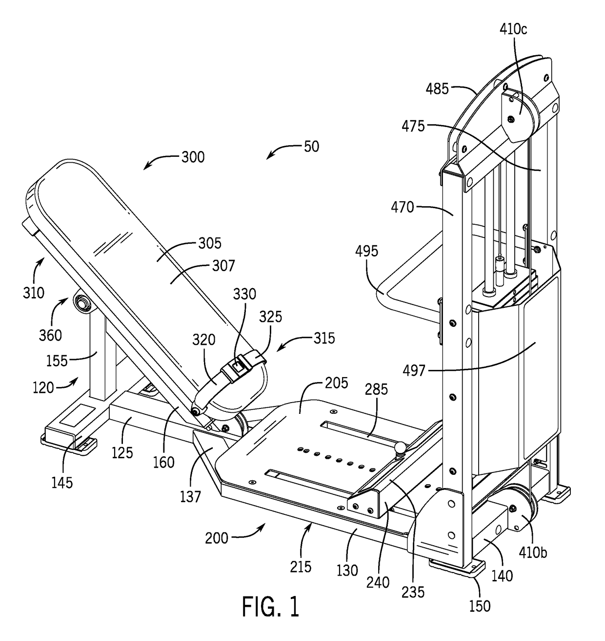
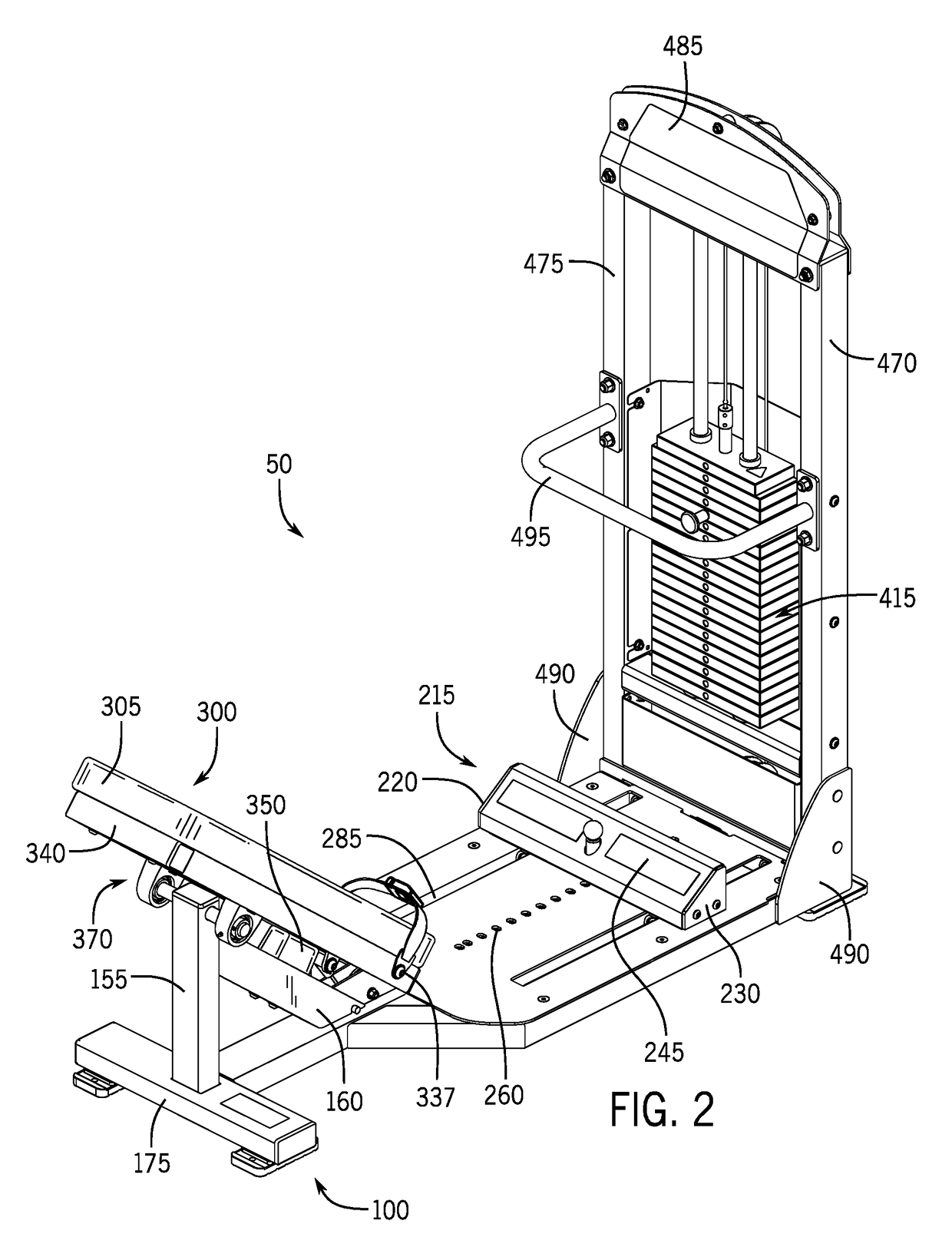
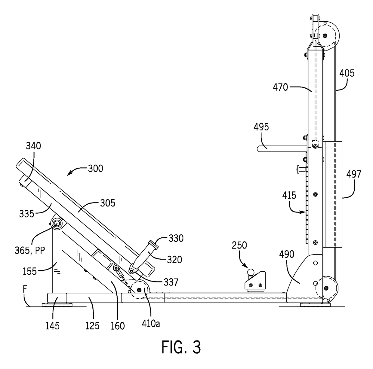
[0046]FIGS. 1-11 depict the apparatus 50 for performing a resisted gluteal bridge movement that is configured for a heavy-use environment, such as in a gym, fitness center or training facility. The exercise apparatus 50 generally comprises (i) a support assembly 100 with a frame assembly 120 and a deck assembly 200; (ii) a bench assembly 300; and, (iii) a resistance assembly 400. The exercise apparatus 50 is designed to be placed on a planar support surface or floor F within the gym, fitness center or training facility. As described in greater detail below, the user or person selects a level of resistance on the resistance assembly 400, secures himself / herself to the bench assembly 300 and then performs at least one repetition of the resisted gluteal bridge movement. Typically, the user performs multiple repetitions of the resisted gluteal bridge movement as part of his / her training regimen.

[0047]Referring to FIGS. 1-11 and as mentioned above, the support assembly 100 includes the f...

second embodiment

[0064]FIGS. 12-19 depict the apparatus 1050 for performing a resisted gluteal bridge movement that is configured for a heavy-to-medium use environment, such as in a gym, fitness center or training facility. The exercise apparatus 1050 generally comprises (i) a support assembly 1100 with a frame assembly 1120 and a deck assembly 1200; (ii) a bench assembly 1300; and, (iii) a resistance assembly 1400. The exercise apparatus 1050 is designed to be placed on a planar support surface or floor F within the gym, fitness center, training facility, or a home. As described in greater detail below, the user or person selects a level of resistance on the resistance assembly 1400, secures himself / herself to the bench assembly 1300 and then performs at least one repetition of the resisted gluteal bridge movement. Typically, the user performs multiple repetitions of the resisted gluteal bridge movement as part of his / her training regimen.

[0065]Referring to FIGS. 12-19 and as mentioned above, the s...

third embodiment

[0080]FIGS. 20-31 depict the apparatus 2050 for performing a resisted gluteal bridge movement that is configured for a lighter use environment, such as in a use in a home gym. The exercise apparatus 2050 generally comprises: (i) a support assembly 2100 with a frame assembly 2120 and a deck assembly 2200; (ii) a bench assembly 2300; and, (iii) a resistance assembly 2400. The exercise apparatus 2050 is designed to be placed on a planar support surface or floor F within the gym, fitness center, training facility, or a home. As described in greater detail below, the user or person selects a level of resistance on the resistance assembly 2400, secures himself / herself to the bench assembly 2300 and then performs at least one repetition of the resisted gluteal bridge movement. Typically, the user performs multiple repetitions of the resisted gluteal bridge movement as part of his / her training regimen.

[0081]Referring to FIGS. 20-31 and as mentioned above, the support assembly 2100 includes ...


PUM


Abstract

The present disclosure provides an exercise apparatus designed to allow a user to perform a gluteal bridge, typically with resistance, to improve the strength of the user's posterior hip and gluteal muscles. The exercise apparatus is configurable for use in different environments—in a gym, fitness center or training facility, a spa or studio, or a home gym. The exercise apparatus includes a frame assembly, a bench assembly, and a resistance assembly. The bench assembly is pivotally connected to the frame assembly to provide an elevated pivot point about which the bench assembly pivots when the user performs the gluteal bridge movement. The resistance assembly is operably connected to the bench assembly and provides a resistance force that the user overcomes in order to pivotally move the bench through the gluteal bridge movement. The resistance assembly can include a cable, pulley and weight stack, or an elastically deformable band.

Description

PRIORITY CLAIM[0001]This application claims priority from U.S. Provisional Patent Application No. 62 / 563,456, filed Sep. 26, 2017, and U.S. Provisional Patent Application No. 62 / 505,542, filed May 12, 2017, all of which are incorporated herein by reference and made a part hereof.TECHNICAL FIELD[0002]This disclosure relates to an exercise apparatus for performing a gluteal bridge movement. In particular, the exercise apparatus is configurable to allow a person to properly perform a resisted gluteal bridge on a repeated basis and where the resistance increases the amount of work to be performed by the person during the exercise.BACKGROUND[0003]Muscles of the human posterior hip, or gluteal muscles, are critical for the task of locomotion. Healthy and / or well-developed gluteal muscles are a key factor in maintaining the strength and health of a person's lower back, hips and knees. Conversely, unhealthy and / or under-developed gluteal muscles have been identified as a significant cause o...

Claims


Application Information

Patent Timeline
Patent Type & Authority Patents(United States)
IPC IPC(8): A63B23/04A63B21/00A63B23/02A63B21/06A63B21/062
CPCA63B23/0482A63B21/4045A63B23/0216A63B2023/0411A63B21/062A63B21/0624A63B21/0628A63B21/06A63B21/005A63B21/008A63B21/0421A63B21/0552A63B23/0222A63B2210/50A63B21/4031A63B21/4009A63B21/4047A63B21/00047A63B21/4029
Inventor KORDECKI, MICHAEL
Owner KORMEL LLC
Why Eureka
Try Eureka