Shielding device and refrigerator comprising same
a shielding device and refrigerator technology, applied in the field of refrigerators, can solve the problems of increased production cost of air doors, increased development cost, and large pressure loss of forced draft fans, and achieve the effects of increasing the effect of discharging moisture, increasing the thread mechanism of shielding devices, and increasing the drainage
- Summary
- Abstract
- Description
- Claims
- Application Information
AI Technical Summary
Benefits of technology
Problems solved by technology
Method used
Image
Examples
first embodiment
hielding Device
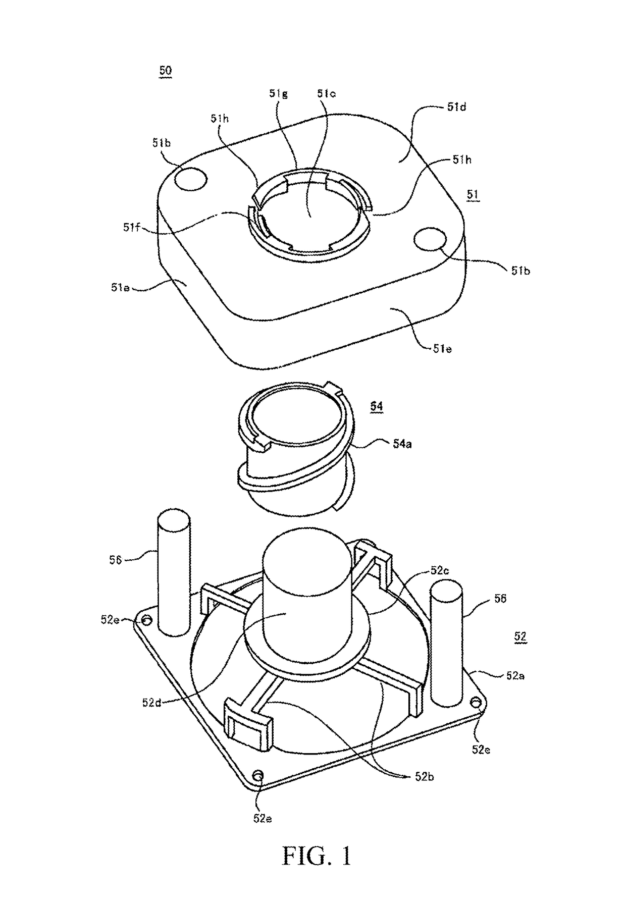
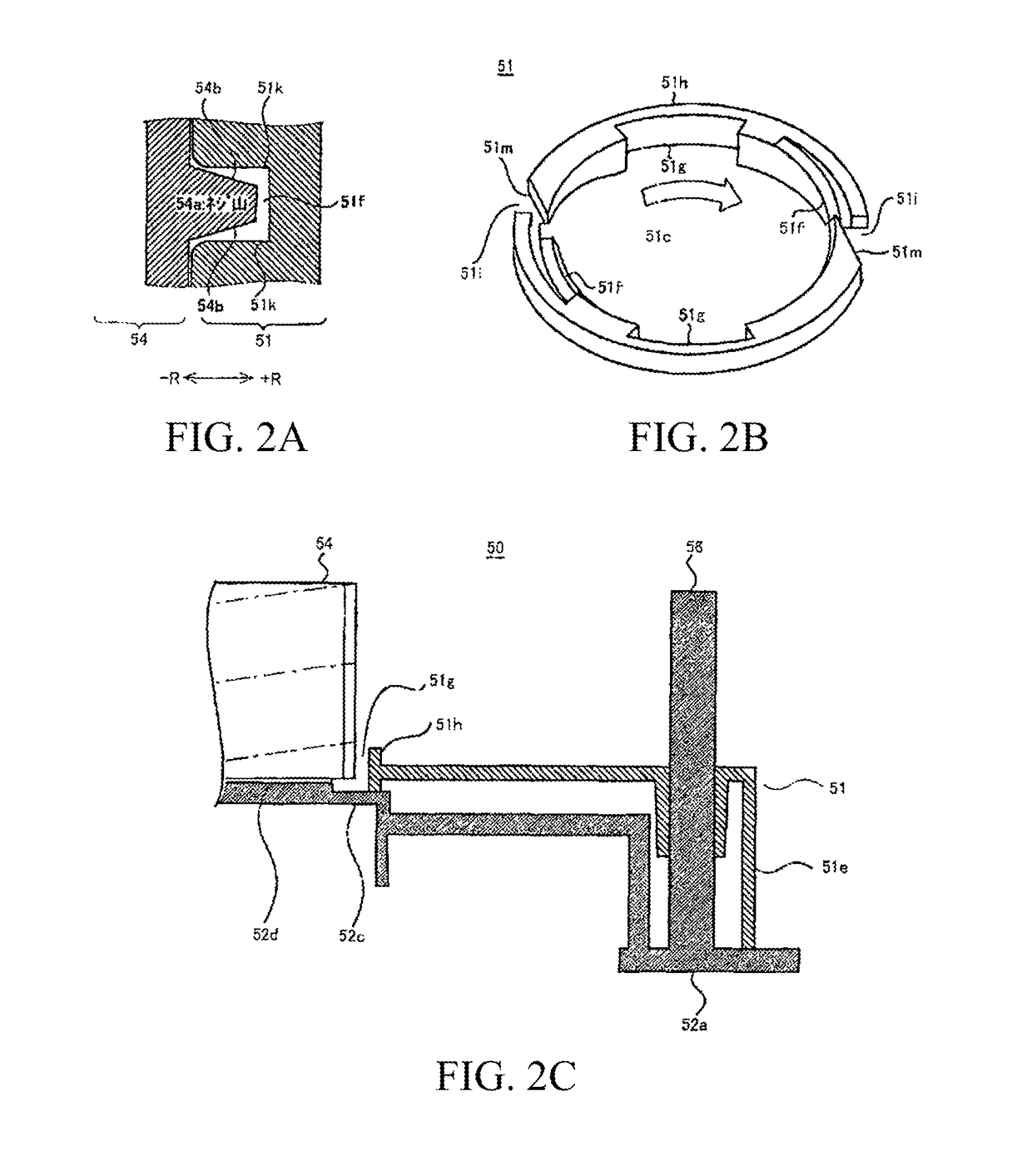
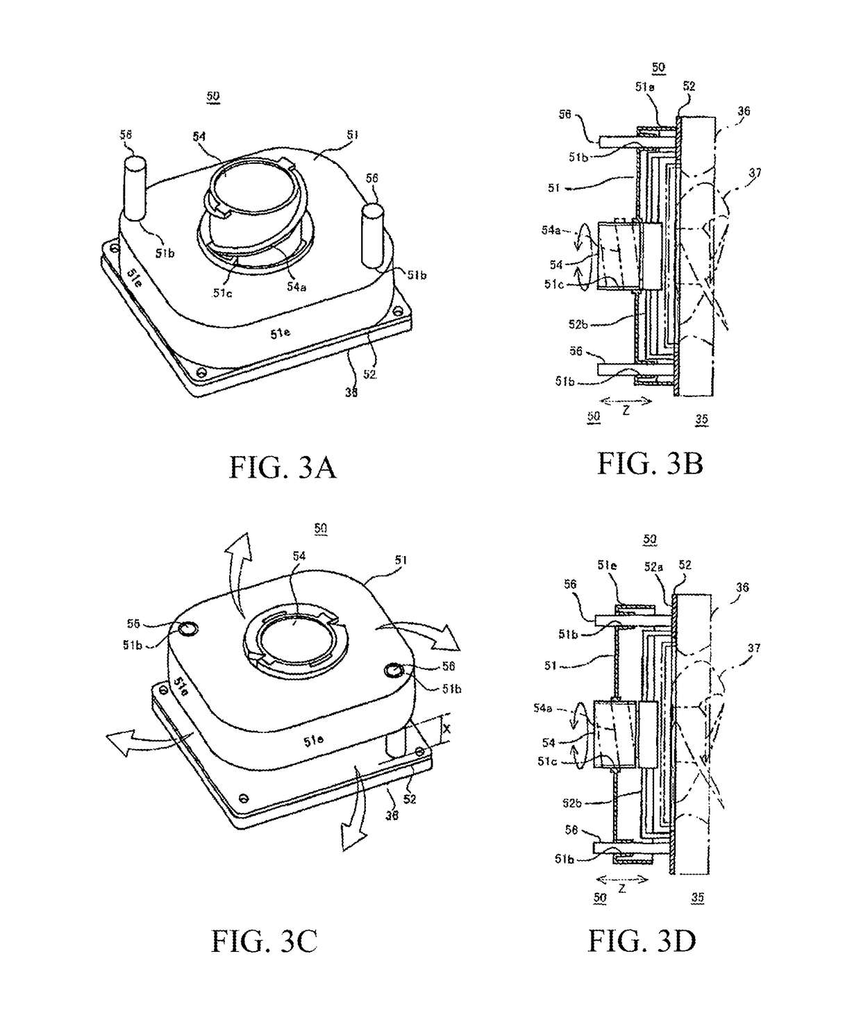
[0047]FIGS. 1, 2A-2C and 3A-3D show the structure of a shielding device 50 according to this exemplary embodiment of the present invention. FIG. 1 is a perspective view indicating that components of the shielding device 50 are decomposed along a longitudinal direction. FIGS. 2A-22C are diagrams of parts of the shielding device 50. FIGS. 3A-3D are diagrams of functions of the shielding device 50.
[0048]Referring to FIG. 1, the shielding device 50 mainly includes a forced draft fan cover 51 substantially cover-shaped, a drive shaft 54 which extends to pass through and drives the forced draft fan cover 51, and a support base 52 used for supporting the forced draft fan cover 51 and the drive shaft 54. Referring to FIG. 7, the main function of the shielding device 50 is inhibiting hot air from leaking to a refrigerating chamber supply air duct 14 during defrosting by closing an open portion of a cooling chamber 13 in a defrosting step.
[0049]In certain embodiments, the force...
second embodiment
frigerator
[0070]Referring to FIG. 4, a forward external view of a schematic structure of a refrigerator 1 is shown according to one embodiment of the present invention. As shown in FIG. 4, the refrigerator 1 of this embodiment has a heat-insulating cabinet 2 as a body, and a storage chamber that stores food and the like is formed inside the heat-insulating cabinet 2. The inside of the storage chamber is partitioned into multiple receiving chambers 3-7 according to different storage temperatures and uses. The uppermost layer of the storage chamber is a refrigerating chamber 3. An ice-making chamber 4 is on a lower left side of the refrigerating chamber 3, while an upper freezing chamber 5 is on a lower right side of the refrigerating chamber 3. A lower layer of the ice-making chamber 4 and the upper freezing chamber 5 is a lower freezing chamber 6. The lowest layer of the storage chamber is a vegetable chamber 7. Besides, the ice-making chamber 4, the upper freezing chamber 5 and the...
third embodiment
of the Refrigerator
[0106]In the following, the working process of the refrigerator 1 having the above structure is described with reference to the figures mentioned above.
[0107]First, the operation of cooling the refrigerating chamber 3 is described. As shown in FIG. 5, the compressor 31 operates, the refrigerating chamber air door 25 is opened, to make the forced draft fan 35 operate, and thus the refrigerating chamber 3 is cooled. That is, air cooled by the cooler 32 sequentially passes through the air supply outlet 13a (forced draft fan 35) of the cooling chamber 13, the refrigerating chamber air door 25, the refrigerating chamber supply air duct 14 and the blowout port 17, to be supplied to the refrigerating chamber 3. Accordingly, food and the like stored in the refrigerating chamber 3 can be cooled and stored at an appropriate temperature.
[0108]At this point, referring to FIG. 7, the shielding device 50 becomes an open state, and the cooling chamber 13 and the refrigerating ch...
PUM
 Abstract
Description
Claims
Application Information
 - R&D
- Intellectual Property
- Life Sciences
- Materials
- Tech Scout
- Unparalleled Data Quality
- Higher Quality Content
- 60% Fewer Hallucinations
Browse by: Latest US Patents, China's latest patents, Technical Efficacy Thesaurus, Application Domain, Technology Topic, Popular Technical Reports.
© 2025 PatSnap. All rights reserved.Legal|Privacy policy|Modern Slavery Act Transparency Statement|Sitemap|About US| Contact US: help@patsnap.com


