Tripod-type constant velocity joint

Active Publication Date: 2019-03-19
NTN CORP
View PDF14 Cites 0 Cited by
  • Summary
  • Abstract
  • Description
  • Claims
  • Application Information

AI Technical Summary

Benefits of technology

The tripod-type constant velocity joint described in this patent allows for the secure connection of driving and driven shafts, even when they are at different angles or off-center. The joint is designed with three outer rings and three tripod members, which can be inclined and swiveled relative to the intermediate member. This prevents fluctuations in the rotational speed of the driven shaft, ensuring constant performance. The design also minimizes the length of the tripod member and prevents damage to the apexes of the tripod member and the outer ring.

Problems solved by technology

However, this constant-velocity joint does not allow the above two center axes to be inclined relative to each other with a relatively large angle, if the above two center axes intersect with each other at a position remote from the joint.
Also, this constant-velocity joint does not allow a large offset between the above two center axes if the center axes are parallel to each other.
However, the connection of the joint cannot be smoothly performed in rare cases.
At this time, if this connection is forcibly performed, the apexes of the bulges and the apexes of the protrusions might be damaged.
Moreover, it turned out that if the tripod member is forcibly pushed into the outer ring in the above state, a pushing force larger than expected is applied thereto, so that the above apexes kept in contact with each other might be damaged.

Method used


Image

  • Tripod-type constant velocity joint
  • Tripod-type constant velocity joint
  • Tripod-type constant velocity joint

Examples


first embodiment

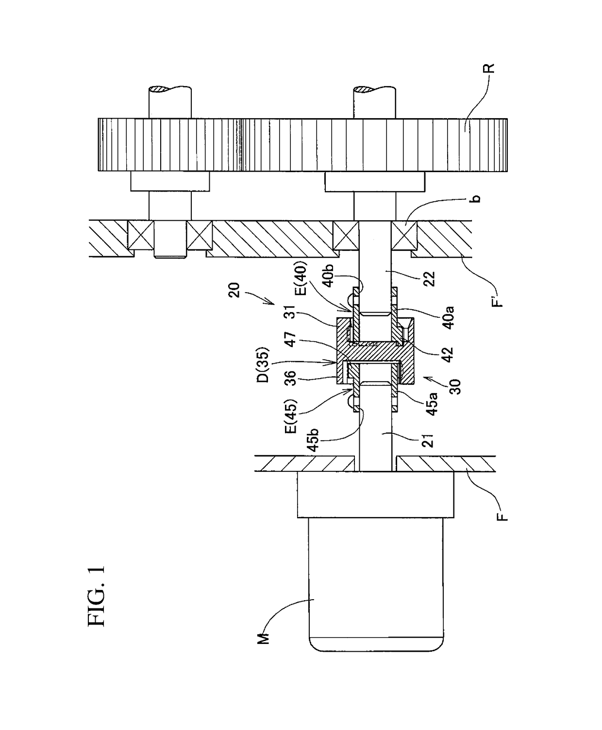
[0078]FIG. 1 illustrates a portion of a rotation transmission mechanism in which a tripod-type constant velocity joint according to the first embodiment of the present invention is used. This rotation transmission mechanism includes a rotary portion R provided with gears through which driving force is transmitted, a driving source M comprising a motor configured to rotate the rotary portion R about the center axis of the rotary portion R, and a driving force transmitting device 20 through which driving force is transmitted from the driving source M to the rotary portion R.

[0079]The driving force transmitting device 20 includes a coupling member comprising the tripod-type constant velocity joint of the first embodiment, through which a driving shaft 21 extending from the driving source M is coupled to a driven shaft 22 (hereinafter sometimes referred to as the “rotary member shaft 22”) extending from the rotary portion R. The coupling member 30 functions to transmit the rotation of t...

second embodiment

[0109]FIG. 7 illustrates a coupling means 30 according to the second embodiment of the present invention. This coupling means 30 is constituted by an intermediate member D, a first shaft end member E connected to the end of the intermediate member D on the side of the rotary member shaft 22, and a second shaft end member E connected to the end of the intermediate member D on the side of the driving shaft 21. The intermediate member D comprises an outer ring 31 arranged on one axial side thereof, and a tripod member 45 arranged on the other axial side thereof. The first shaft end member E comprises a tripod member 40 connected to the outer ring 31, and the second shaft end member E comprises an outer ring 36 connected to the tripod member 45.

[0110]The connection structure between the tripod member 40 and the outer ring 31, which is located on one axial side of the intermediate member D, and the connection structure between the outer ring 36 and the tripod member 45, which is located ...

third embodiment

[0114]FIG. 8 illustrates a portion of a rotation transmission mechanism in which a tripod-type constant velocity joint according to the third embodiment of the present invention is used. This rotation transmission mechanism includes a rotary portion R provided with gears through which driving force is transmitted, a driving source M comprising a motor configured to rotate the rotary portion R about the center axis of the rotary portion R, and a driving force transmitting device 20 through which driving force is transmitted from the driving source M to the rotary portion R.

[0115]The driving force transmitting device 20 includes a coupling means 30 comprising the tripod-type constant velocity joint of the third embodiment, through which a driving shaft 21 extending from the driving source M is coupled to a driven shaft 22 (hereinafter sometimes referred to as the “rotary member shaft 22”) extending from the rotary portion R. The coupling means 30 functions to transmit the rotation of ...


PUM


Abstract

A tripod-type constant velocity joint includes an intermediate member, and first and second tripod members connected to the respective ends of the intermediate member. The intermediate member includes first and second outer rings. The first tripod member is formed with three protrusions, and the second tripod member is formed with three protrusions. The first outer ring is formed in its inner periphery with three axially extending first track grooves which are open at its axial end surface. The second outer ring is formed in its inner periphery with three axially extending second track grooves which are open at its axial end surface. The protrusions of the first tripod member are axially slidably received in the respective first track grooves. The protrusions of the second tripod member are axially slidably received in the respective second track grooves.

Description

TECHNICAL FIELD[0001]The present invention relates to a constant velocity joint through which a driving shaft and a driven shaft are coupled together such that the motive power of the driving shaft is transmitted to the driven shaft through the constant velocity joint.BACKGROUND ART[0002]Constant velocity joints have been known as components for transmitting the torque of a drive shaft of an automobile to an axle of the automobile.[0003]Since constant velocity joints allow the angular displacement between a driving shaft and a driven shaft while keeping the speed of the driving and driven shafts constant, they are being used not only in automobiles but also in various industrial machines, home appliances, office machines, etc.[0004]There are two types of constant-velocity joints, namely, fixed constant-velocity joints, which only permits an angular displacement, and sliding constant-velocity joints, which permit both angular and axial displacements. Japanese Unexamined Patent Applic...

Claims


Application Information

Patent Timeline
IPC IPC(8): F16D3/202F16D3/72F16D3/205
CPCF16D3/72F16D3/2055
Inventor FUKUZAWA, SATORUYAMAOKA, KENJIFUJITSUKA, IKUMA
Owner NTN CORP
Why Eureka
Try Eureka