Infrared microscope

a microscope and infrared technology, applied in the field of infrared microscopes, can solve the problems of inability to obtain sufficient spatial resolution, inability to avoid, shorten measurement time, etc., and achieve the effect of reducing crosstalk, reducing crosstalk, and measuring with good accuracy

Active Publication Date: 2019-03-19
JASCO CORP
View PDF10 Cites 0 Cited by
  • Summary
  • Abstract
  • Description
  • Claims
  • Application Information

AI Technical Summary

Benefits of technology

[0027]According to the infrared microscope of the present invention, disposing the first aperture having a plurality of holes between the light source and the sample, and disposing the second aperture corresponding to the first aperture between the sample and the detector (disposing the second aperture at an imaging point of the infrared light at the first aperture) enable the holes to obtain confocal effect simultaneously, and measurement with good accuracy and less crosstalk becomes possible. Further, a plurality of the first and the second aperture is provided, respectively, so that a suitable aperture can be selected in accordance with the sample to be measured and the wavelength the infrared light for measurement. For example, a conventional aperture can be used when the wavelength of the infrared light is short, and an aperture having plurality of holes can be used when the wavelength of the infrared light is long for reducing crosstalk.

Problems solved by technology

These methods shorten measurement time compared to measurement methods which uses general spot irradiation.
However, crosstalk, which spectra overlap each other, cannot be avoided, and sufficient spatial resolution cannot be obtained.

Method used


Image

  • Infrared microscope
  • Infrared microscope
  • Infrared microscope

Examples


first embodiment

The First Embodiment

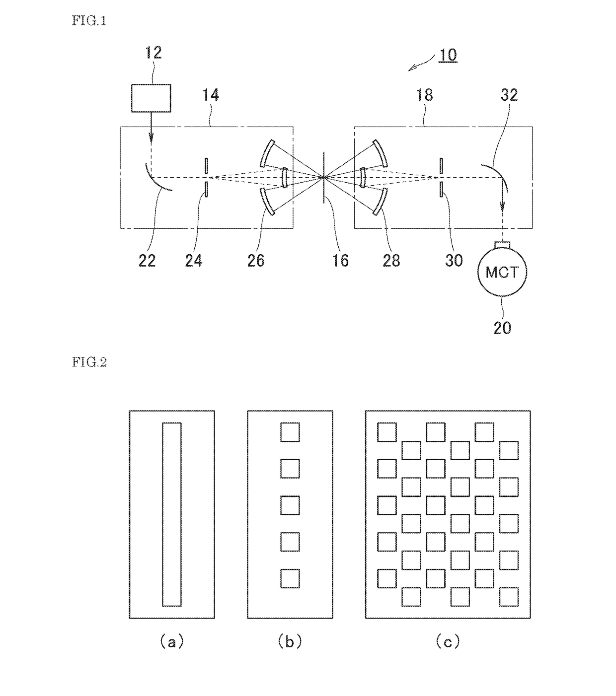
[0036]FIG. 1 is a schematic diagram of the infrared microscope according to the first embodiment of the present invention. It is a simplified schematic configuration, so that explanation of the present embodiment becomes easier. Therefore, although it is not shown in FIG. 1, configuration components which are necessary for general microscopes such as a movable stage for placing the sample, a computer for analyzing, the detection light, and the like are comprised. The infrared microscope 10 shown in FIG. 1 comprises a light source 12 for irradiating an infrared light, an infrared light irradiating optical system 14 for irradiating the emitted infrared light to a sample 16, an infrared light focusing optical system 18 for focusing the infrared light transmitted through the sample 16, and a MCI detector 20 for detecting the focused infrared light.

[0037]Characteristic features of the present invention are that the infrared light irradiating optical system 14 comprise...

second embodiment

The Second Embodiment

[0051]Next, an infrared microscope according to the second embodiment of the present invention is described in detail with reference to figures. Configurations in common with the infrared microscope 10 of the first embodiment shown in FIG. 1 are represented with reference numbers of which 100 are added respectively.

[0052]FIG. 5 is a schematic diagram of the infrared microscope according to the second embodiment of the present invention. The infrared microscope 110 shown in FIG. 5 comprises a light source 112 for irradiating an infrared light, an infrared light irradiating optical system 114 for irradiating the emitted infrared light to a sample 116, an infrared light focusing optical system 118 for focusing the infrared light transmitted through or reflected by the sample 116, and a MCT detector 120 for detecting the focused infrared light.

[0053]The present embodiment is an embodiment which uses the present invention to a Fourier transform infrared spectrometer ...

third embodiment

[0064]Next, an infrared microscope according to a third embodiment of the present invention is described with reference to the figures. Configurations in common with the infrared microscope 110 of the second embodiment shown in FIG. 5 are represented with reference numbers of which 100 are added respectively.

[0065]FIG. 6 is a schematic diagram of the infrared microscope according to the third embodiment of the present invention. The infrared microscope 210 shown in FIG. 6 comprises: a light source 212 for emitting an infrared light; an infrared light irradiating optical system 214 for irradiating the emitted infrared light to a sample 216; an infrared light focusing optical system 218 for focusing the infrared light transmitted through or reflected by the sample 216; and a MCT detector 220 for detecting the focused infrared light. The present embodiment is also an embodiment that uses the present invention to a similar FTIR like the second embodiment.

[0066]A characteristic feature o...


PUM

PropertyMeasurementUnit
wavelengthaaaaaaaaaa
infrared microscopeaaaaaaaaaa

Abstract

The problem to be solved by the present invention is to provide an infrared microscope with good measuring accuracy and less crosstalk.The infrared microscope 10 comprises a light source 12, an irradiating unit 14 for irradiating the infrared light from the light source to a sample 16, a focusing unit 18 for focusing the infrared light transmitted through or reflected by the sample 16, and a detector 20 for detecting the focused infrared light. The irradiating unit 14 comprises a first aperture 24, and the first aperture is disposed at a position where the infrared light from the light source passes therethrough. The focusing unit 18 comprises a second aperture 30, and the second aperture is disposed at an imaging position of the infrared light at the first aperture 24. The first aperture has a plurality of holes, and the holes are disposed at intervals corresponding to the arrangement of the light-receiving elements provided in the detector 20 to detect the infrared light as a detecting light. The second aperture 30 has holes that have the same size and arrangement as the first aperture 24.

Description

RELATED APPLICATIONS[0001]This application claims the priority of Japanese Patent Application No. 2017-82515 filed on Apr. 19, 2017, the disclosure of which is incorporated herein by reference in its entirety.FIELD OF THE INVENTION[0002]The present invention relates to infrared microscopes, and particularly to improvements in apertures in infrared microscopes for obtaining high spatial resolution.BACKGROUND OF THE INVENTION[0003]Conventionally, infrared microscopes as means for obtaining optical information of microscopic parts on samples are known. For example, to investigate molecular structures of organic substances attached to a surface of an individual, infrared microscopes irradiate infrared light to a microscopic part on a sample held by a stage and detect transmitted or reflected infrared light by a detector to measure absorption spectrum and the like.[0004]Recently, measurement methods which irradiate linear infrared light to a sample (linear irradiation) to obtain spectra ...

Claims


Application Information

Patent Timeline
Patent Type & Authority Patents(United States)
IPC IPC(8): G02B21/00G01N21/35
CPCG02B21/0032G02B21/0048G02B21/006G01N21/35
Inventor AIZAWA, KENTOSUGIYAMA, HIROSHIKOSHOBU, JUN
Owner JASCO CORP
Why Eureka
Try Eureka