Electrooptical apparatus and electronic device

a technology of electrooptical apparatus and electronic device, which is applied in the direction of electrical apparatus casings/cabinets/drawers, television systems, and casings with display/control units. it can solve the problems of difficult to secure the terminal disposing region, difficult to drive the electrooptical apparatus at a high speed, and the pitch interval between the panel terminals is limited, so as to achieve high speed and improve the effect of display quality

Active Publication Date: 2019-03-19
SEIKO EPSON CORP
View PDF14 Cites 2 Cited by
  • Summary
  • Abstract
  • Description
  • Claims
  • Application Information

AI Technical Summary

Benefits of technology

[0005]An advantage of some aspects of the invention is to provide an electrooptical apparatus provided with a plurality of terminal groups which is capable of driving at a high speed. In addition, another advantage is to improve a display quality in the electrooptical apparatus provided with the plurality of terminal groups.
[0007]According to the electrooptical apparatus, a difference between a transmission delay time of the video signal which is transmitted from the first terminal group to the display control circuit and a transmission delay time of the video signal which is transmitted from the second terminal group to the display control circuit can be reduced. Accordingly, the electrooptical apparatus can be driven at a high speed.
[0009]According to the aspect, the difference between the transmission delay time of the video signal being transmitted from the first terminal group to the display control circuit and the transmission delay time of the video signal being transmitted from the second terminal group to the display control circuit can be further reduced.
[0011]According to the aspect, since a wiring length of the signal wiring for the video signal which passes through the second terminal group can be shortened, the electrooptical apparatus can be driven at a high speed.
[0013]According to the aspect, since a capacitance between the two terminals adjacent to each other in the first terminal group and the signal wiring of the video signal from the second terminal group passing through between the two terminals can be reduced, cross coupling between the video signals can be reduced.
[0015]According to the aspect, the signal wiring transmitting the video signal from the second terminal group is capable of reasonably passing through between the adjacent two terminals of the first terminal group.

Problems solved by technology

Meanwhile, there is a limitation for a pitch interval between the panel terminals.
Therefore, it becomes more difficult to secure a terminal disposing region where the panel terminals and the flexible substrate are connected to each other as the high resolution increase.
Therefore, driving of the electrooptical apparatus at a high speed becomes difficult.
In addition, a component in a high frequency band of the video signal which passes through the terminal group distant away from the opposite substrate and is input to the display control circuit tends to be more deteriorated than a component in a high frequency band of the video signal which passes through the terminal group close to the opposite substrate and is input to the display control circuit.
Accordingly, since the video signals having different frequency characteristics are supplied to the display control circuit, there is a problem in that a display quality is deteriorated.
In this case, since the electrostatic noise is sufficiently attenuated by the protection circuit, the electrostatic noise passing through the curved part is weak.

Method used


Image

  • Electrooptical apparatus and electronic device
  • Electrooptical apparatus and electronic device
  • Electrooptical apparatus and electronic device

Examples


embodiment

A. Embodiment

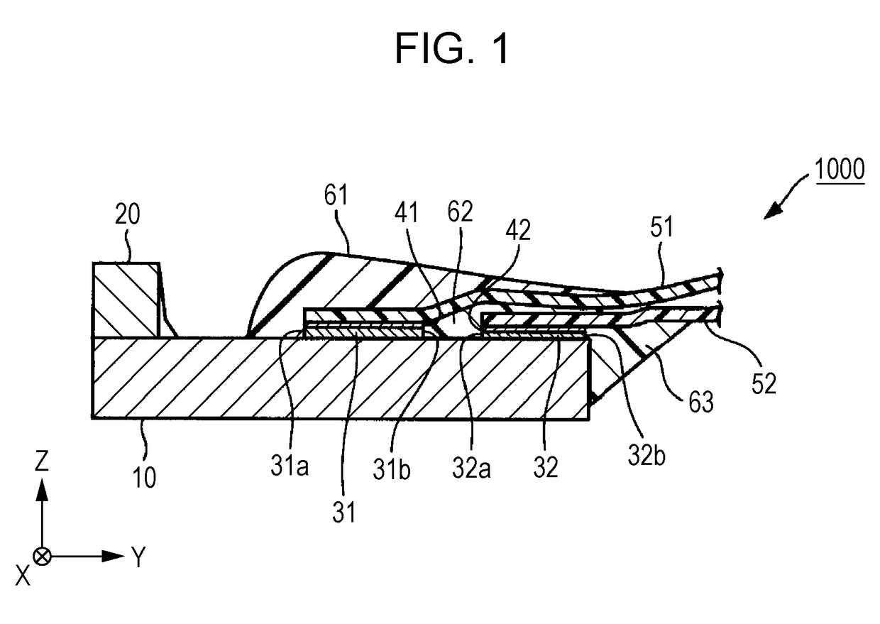
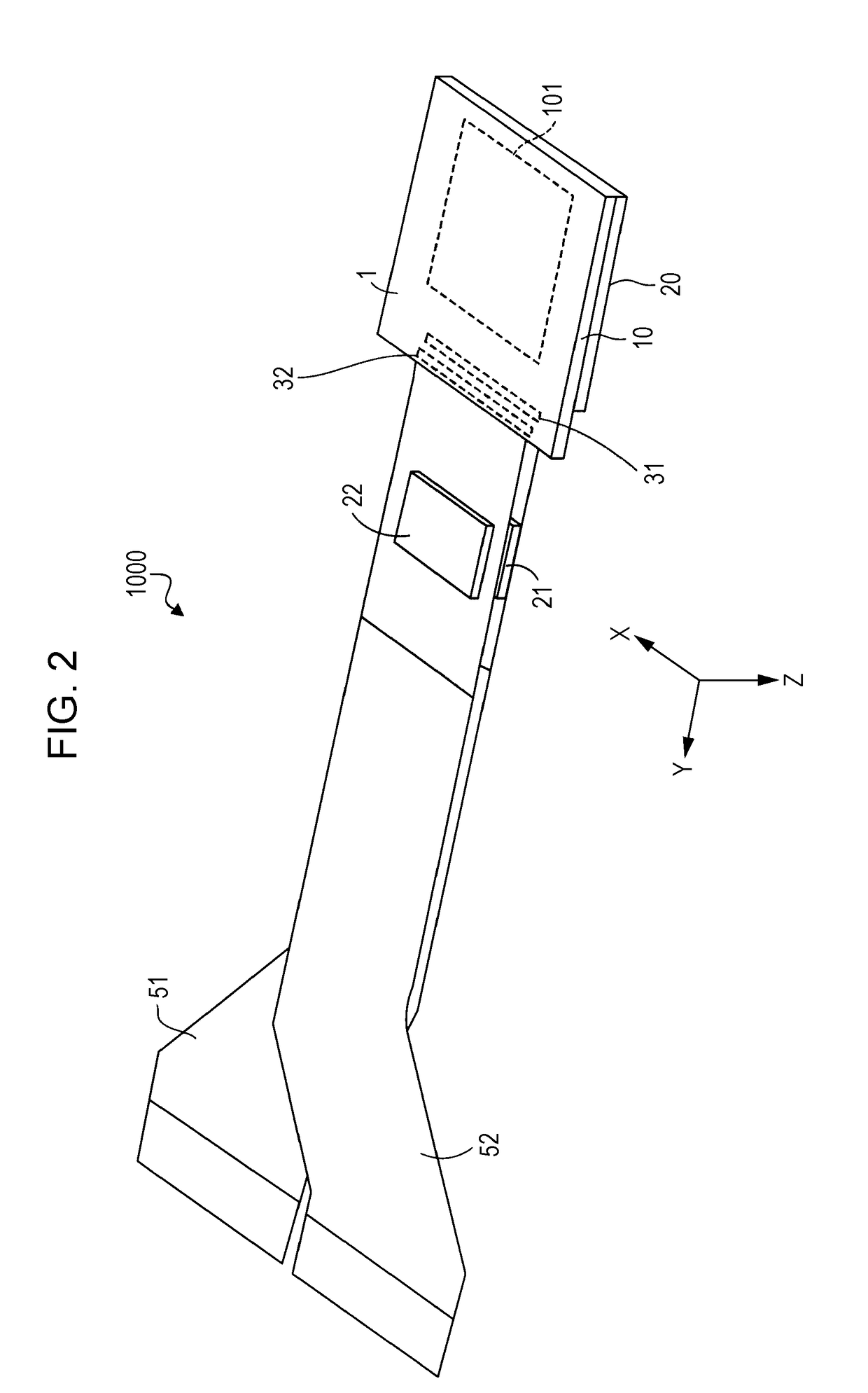
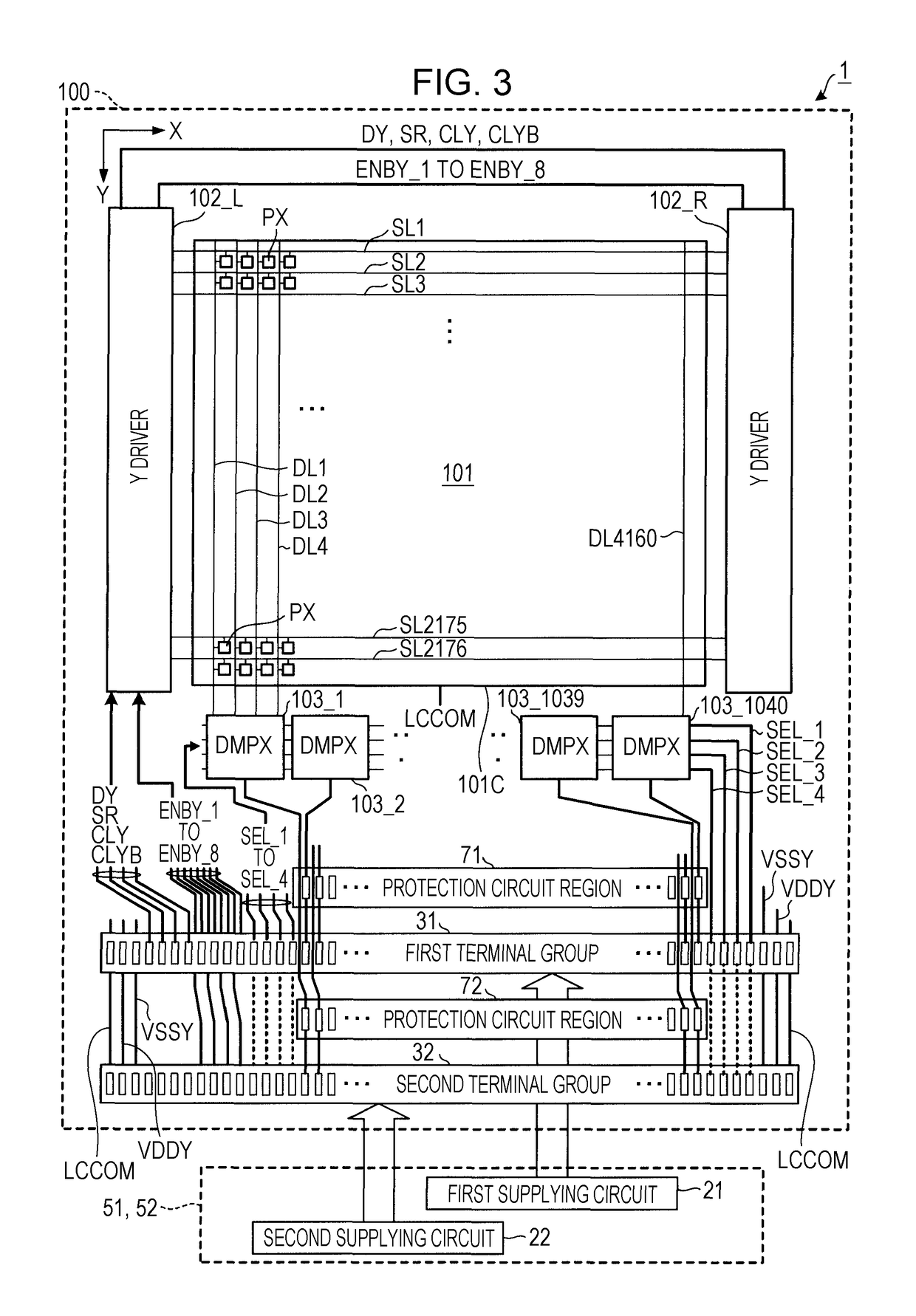
[0030]FIG. 1 is a left side view of an electrooptical apparatus 1000 which is an embodiment of the invention, and FIG. 2 is a perspective view of the electrooptical apparatus 1000. The electrooptical apparatus 1000 constitutes a liquid crystal displaying apparatus of an active matrix type which is a displaying unit of a small electronic device such as a projection type projector. The electrooptical apparatus 1000 is provided with an electrooptical panel 1, a first supplying circuit 21, a second supplying circuit 22, a first flexible circuit substrate (flexible printed circuit) 51, and a second flexible circuit substrate 52. Also, the electrooptical apparatus 1000 may have, for example, the number of pixels of 3840×2160 which is the number of pixels of a full Hi-vision being doubled in a vertical direction and doubled in a horizontal direction. In addition, each of the first supplying circuit 21 and the second supplying circuit 22 is, for example, an integrated circuit f...

modification example

B. Modification Example

[0109]Hitherto, the embodiment of the invention is described, but of course the embodiment may be modified as follows.

B-1

[0110]In the embodiment as described above, the connection destinations of a half of eight signal wirings for supplying the enable signals are set as the first terminal group 31, and the connection destinations of the other half thereof are set as the second terminal group 32; however, it is only an example, the number of the signal wirings for the enable signals connecting to the first terminal group 31 and the number of the signal wirings for the enable signals connecting to the second terminal group 32 may be changed. That is, the number of the signal wirings for the enable signals connecting to the first terminal group 31 and the number of the signal wirings for the enable signals connecting to the second terminal group 32 are adjusted, such that both power consumption of the first supplying circuit 21 on the first flexible substrate 51 ...

application example

C. Application Example

[0113]FIG. 10 is a schematic diagram of a projection type displaying apparatus (three-plate type projector) 3000 to which the electrooptical apparatus 1000 is applied. The projection type displaying apparatus 3000 is configured with three electrooptical apparatuses 1 (1R, 1G, and 1B) corresponding to different display colors (red, green, and blue) from one another. An illumination optical system 3001 supplies a red component r in an emitting light beam from a light emitting device (light source) 3002 to the electrooptical apparatus 1R, supplies a green component g to the electrooptical apparatus 1G, and supplies a blue component b to the electrooptical apparatus 1B. Each electrooptical apparatus 1000 functions as a modulator (light valve) which modulates each monochromatic light supplied from the illumination optical system 3001 in accordance with a display image. A projection optical system 3003 synthesizes the emitting light from each the electrooptical appar...


PUM


Abstract

An electrooptical apparatus includes an element substrate of which a first terminal group and a second terminal group for connecting each flexible substrate are sequentially formed thereon from a displaying portion. A signal wiring for supplying a video signal to a display control circuit for driving the displaying portion is dispersed and connected to the first terminal group and the second terminal group. In addition, a resistance of the signal wiring for the video signal which passes through the first terminal group and reaches the display control circuit and a resistance of the signal wiring for the video signal which passes through the second terminal group and reaches the display control circuit are substantially equal to each other.

Description

BACKGROUND1. Technical Field[0001]The present invention relates to an electrooptical apparatus in which a flexible substrate such as a tape carrier package (TCP), a flexible printed circuit (FPC), or a chip on film (COF) is disposed on a terminal group provided on a substrate, and an electronic device.2. Related Art[0002]Generally, an electrooptical apparatus provided with a liquid crystal panel (liquid crystal light valve) connects the liquid crystal panel and a flexible substrate to each other, and supplies the number of video signals corresponding to the number of data lines from the flexible substrate. In order to realize a high resolution of the electrooptical apparatus, the number of panel terminals needs to be increased. Meanwhile, there is a limitation for a pitch interval between the panel terminals. Therefore, it becomes more difficult to secure a terminal disposing region where the panel terminals and the flexible substrate are connected to each other as the high resoluti...

Claims


Application Information

Patent Timeline
Patent Type & Authority Patents(United States)
IPC IPC(8): H05K1/02H02H7/20H05K5/00H04N5/14
CPCH05K1/0216H02H7/20H05K5/0017H05K1/028H04N5/14G02F1/13452G09G3/3696G09G2300/0426G09G2320/0223G09G2330/04
Inventor YOSHII, MASAHITO
Owner SEIKO EPSON CORP
Why Eureka
Try Eureka