Filter material for fluids and method for producing a filter material

Active Publication Date: 2019-03-26
HYDAC FILTERTECHNIK GMBH
View PDF31 Cites 0 Cited by
  • Summary
  • Abstract
  • Description
  • Claims
  • Application Information

AI Technical Summary

Benefits of technology

[0005]An object of the invention is to provide an improved filter material that can be pro

Problems solved by technology

The joining of the two layers by needl

Method used


Image

  • Filter material for fluids and method for producing a filter material
  • Filter material for fluids and method for producing a filter material
  • Filter material for fluids and method for producing a filter material

Examples


Embodiment Construction

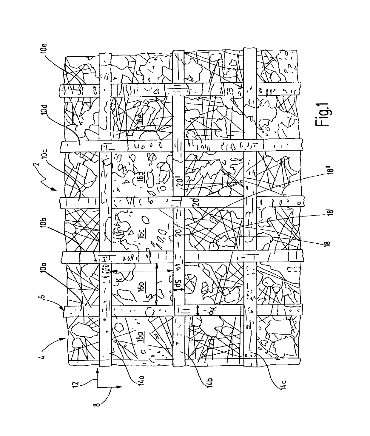
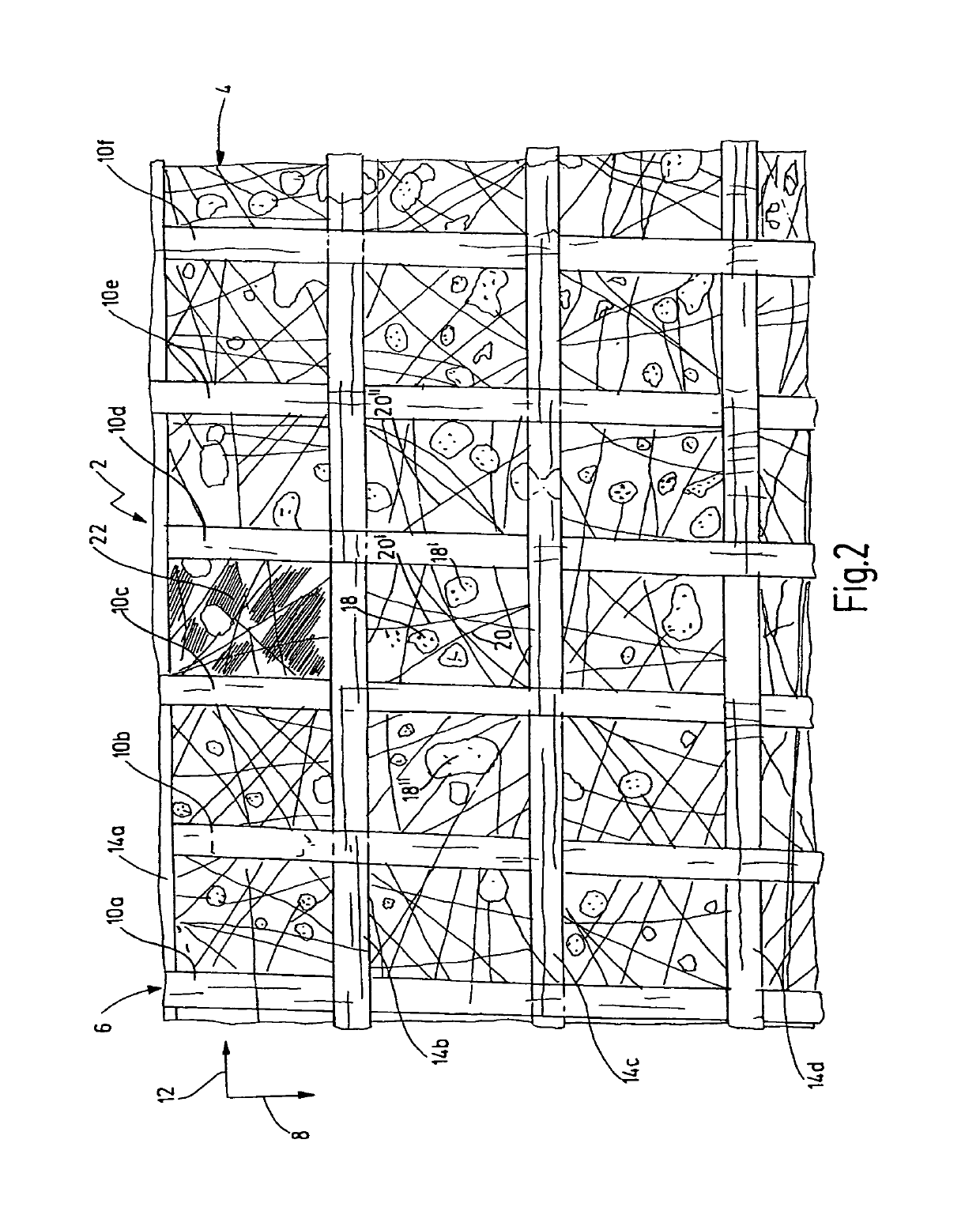
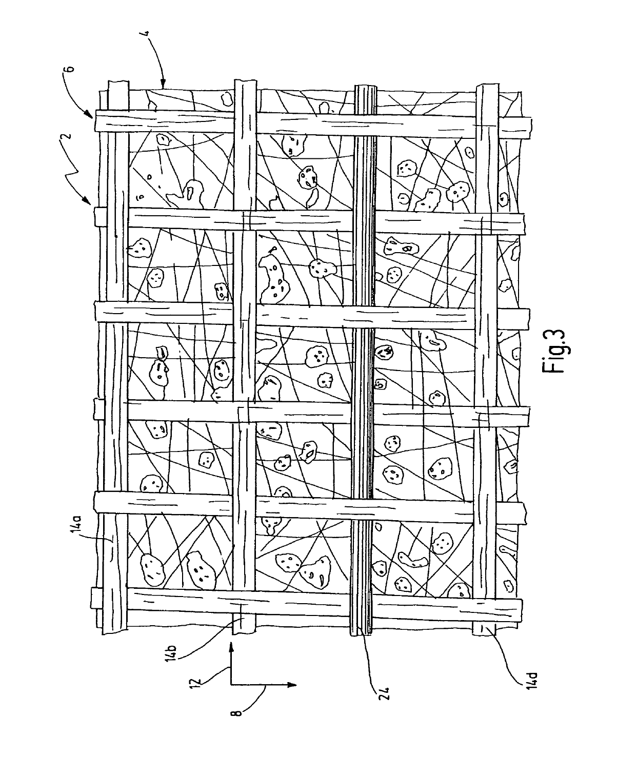
[0032]FIG. 1 shows a rectangular section of a filter material 2 that has a flat shape and several layers of a filter medium 4 and a support structure 6. The filter medium 4 is produced from a plastic nonwoven in one layer. The support structure 6 comprises thread elements 10a, 10b, 10c, 10d, 10e extending in a warp direction 8 and other thread elements 14a, 14b, 14c extending in a weft direction 12. The thread elements 10a, 10b, . . . , 14a, 14b, . . . form a regular woven fabric, in the manner of a plain weave, with the thread elements 10a, 10b, . . . , 14a, 14b, . . . each being woven in alternation at crossing sites over and then under the next thread element 10a, 10b, . . . , 14a, 14b, . . . . The thread elements 10a, 10b, . . . , 14a, 14b, . . . have essentially the same thickness dS, dK, The values for dK are, for example, 246 μm and 262.4 μm; the values for dS are, for example, 252.6 μm and 242.8 μm. Moreover, the thread elements 10a, 10b, . . . , and 14a, 14b, . . . extendin...


PUM

PropertyMeasurementUnit
Thicknessaaaaaaaaaa
Thicknessaaaaaaaaaa
Thicknessaaaaaaaaaa

Abstract

A filter material (2) for fluids, in particular hydraulic fluids, includes a filter medium (4) having at least one layer, and a supporting structure (6) partially made of a plastic material and resting flatly in some surface areas on at least one side of the filter medium (4). The filter medium (4) and the supporting structure (6) are connected to one another by laminating, covering and/or by a melting process.

Description

FIELD OF THE INVENTION[0001]The invention relates to a filter material for fluids, in particular for hydraulic fluids, comprising a filter medium having at least one layer and a support structure formed at least partially from a plastic material and adjoining at least one side of the filter medium in surface regions, and to method for producing such a filter material.BACKGROUND OF THE INVENTION[0002]Filter materials for producing interchangeable filter elements in hydraulic systems are known in diverse configurations and include, for example, of a filter nonwoven, preferably of several layers, with a support structure on one or both sides (incident flow side or outflow side). A hydraulic fluid to be filtered flows through these types of filter elements, in part with a considerable pressure difference arising from the unfiltered side to the filtered side. To be able to withstand this pressure difference and dynamic flow forces in the unfiltered material, the filter materials from whi...

Claims


Application Information

Patent Timeline
IPC IPC(8): B01D39/14B05D5/00B01D39/08B32B37/00D03D15/00D03D1/00B01D39/16
CPCB01D39/14B01D39/083B01D39/1623B05D5/00B32B37/00D03D1/00D03D15/0094Y10T156/10B01D2239/0478B01D2239/0654B01D2239/0668B01D2239/0681D10B2505/04D03D15/43
Inventor SCHWENDER, MATTHIASSCHMITZ, ANDREASKOCH, EDWIN
Owner HYDAC FILTERTECHNIK GMBH
Why Eureka
Try Eureka