Hydraulic accumulator, especially bladder accumulator

a technology of accumulators and bladders, applied in the field of bladder accumulators, can solve the problems of adversely affecting operation reliability, high production costs, and machinery increasing production costs, and achieve the effects of increasing operating reliability, reducing production costs, and reducing maintenance costs

Inactive Publication Date: 2005-04-05
HYDAC TECH GMBH
View PDF12 Cites 0 Cited by
  • Summary
  • Abstract
  • Description
  • Claims
  • Application Information

AI Technical Summary

Benefits of technology

Objects of the present invention are to provide a hydraulic accumulator which can be produced comparatively easily and economically, and simultaneously has increased operating reliability and longer maintenance intervals.
By eliminating a separate valve structure installed in the connecting piece, the cost for production, machining and assembly is greatly reduced. With the approach of the present invention, the valve body can be made as a component of the valve support in the manner of an insertion module. The insertion module can be quickly and easily inserted into the fluid connecting piece and can be retained to be able to move lengthwise therein. With respect to the modular structure, in the manner of a module, adaptations to altered size rations, especially with respect to the connecting piece, for the hydraulic accumulator can be quickly and easily done. Furthermore, the required number of fluid passages in the valve support can be structurally provided easily and economically.
The arrangement of the energy accumulator also supports the modular structure of the approach. The energy accumulator can be easily and economically inserted into the connecting piece.
Since the valve support is guided on its outer periphery side along the inside circumference of the connecting piece, the guide surface can be enlarged such that secure, fitted guidance can be achieved. This arrangement increases the operating reliability of the present invention. Furthermore, the sealing system which is subject to wear can be completely abandoned.
Based on the plate-like configuration of the valve body, flat contact of the separating element takes place so that flat actuation takes place carefully. This actuation likewise helps to reduce wear, and consequently, benefits the operating reliability of the hydraulic accumulator of the present invention.
In one preferred embodiment of the hydraulic accumulator of the present invention, the stop is formed by a sealing ring which fits into a recess on the inside periphery of the connecting piece. The sealing ring can then be reliably inserted by a mounting groove on the outside periphery of the valve support into the recess on the connecting piece. With a simple catch process against the action of the compression spring, in only one process the insertion module can be completely installed. The path between the stop and the end-sided outlet of the mounting groove is made especially larger than the free path of travel of the valve body from the maximum possible open position to its completely closed position in order to later achieve unhindered operation of the valve body with the valve support and to enable installation.

Problems solved by technology

The disadvantage of the conventional valve arrangement is the resulting high production costs due to the required expenditures for producing and machining of a plurality of individual parts as a result of this valve design.
This machinery likewise increases production costs, due at least to the valve plate of the valve body being produced by forging.
In this respect, the known approach has a complex structure to increase production costs and accordingly, adversely affect operating reliability.
This approach has only one fluid passage in the valve body and is likewise complex and expensive to produce.

Method used


Image

  • Hydraulic accumulator, especially bladder accumulator
  • Hydraulic accumulator, especially bladder accumulator
  • Hydraulic accumulator, especially bladder accumulator

Examples


Embodiment Construction

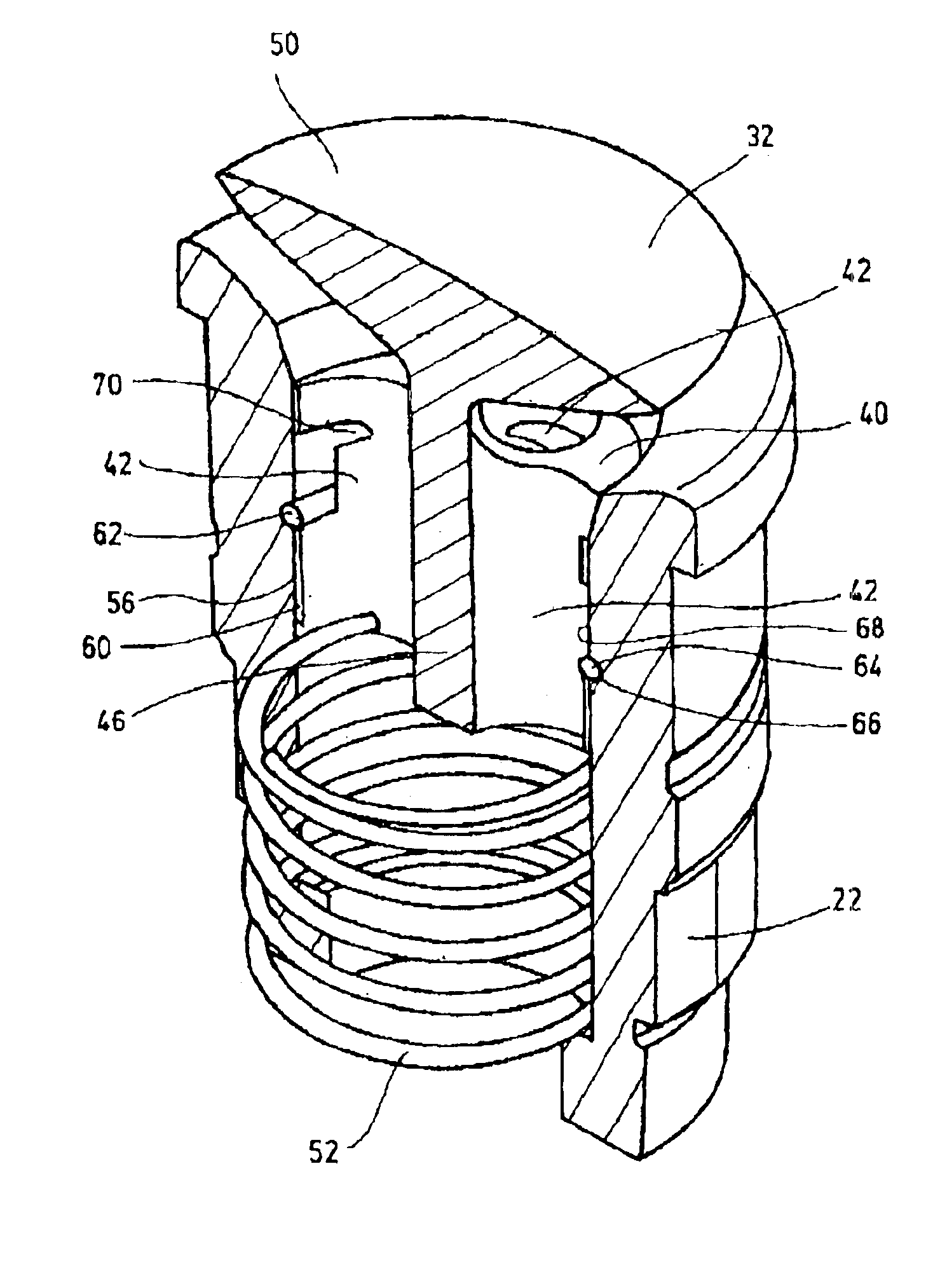
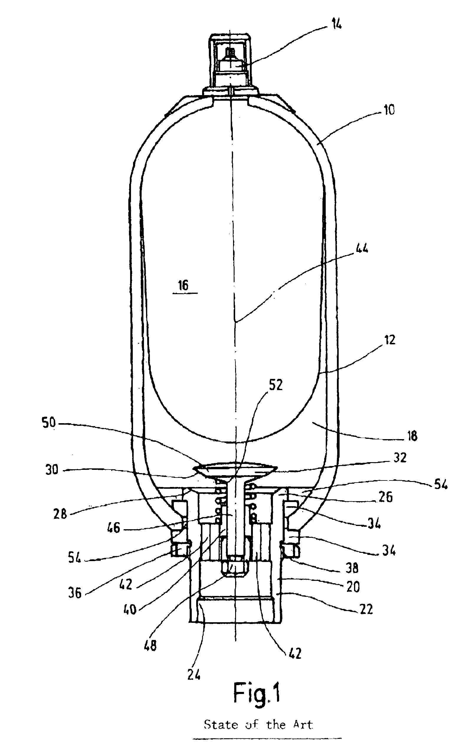
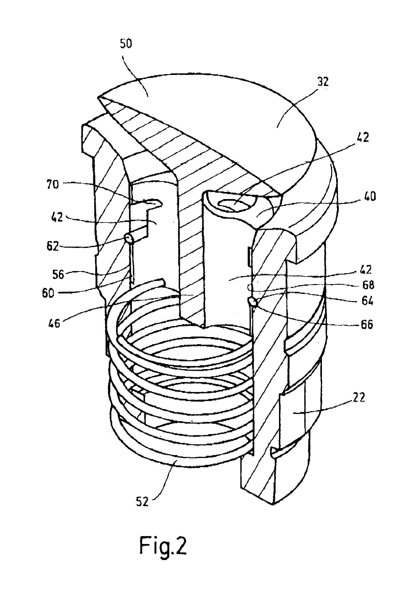
FIG. 1 shows a conventional bladder accumulator with an accumulator housing 10 made as a pressurized housing. In the accumulator housing 10, an elastically flexible separating element 12 separates the gas chamber 16 which borders the gas-side access 14 from the fluid chamber 18 which borders the fluid-side access 20. The fluid-side access 20 has a fluid connecting piece 22 made in the form of a hollow cylinder. In FIG. 1, the connecting piece 22 on its lower inner side has a connecting point 24 with internal threads to which a fluid line can be connected. On its opposite end, the connecting piece 22 has a widened area 26 with an inner peripheral side provided with a contact bevel 28 for contacting the lower plate edge 30 of the valve body 32 in its closed position (not shown). To fix the fluid connecting piece 22 on the lower open end of the accumulator housing 10, fixing rings 34 are located within and outside of the accumulator housing 10. For bracing of the fixing rings 34 agains...


PUM


Abstract

A hydraulic accumulator, especially a bladder accumulator, includes an accumulator housing (10), and a separation element disposed in and separating the accumulator housing interior into a gas chamber (16) adjoining an inlet (14) on the gas side from a fluid chamber (18) adjoining an inlet (20) on the fluid side. The inlet on the fluid side has a fluid connecting neck (22) having a valve support (40) disposed in the neck. The valve support has fluid openings (42), and a disk-shaped valve body (32) that tapers towards the valve shaft (46) on its side facing the valve support (40). The valve shaft can be pretensioned via a force accumulator (62) into the open position releasing the fluid opening, can be displaced into its closed position by a displacement of the separation element (12), and projects into the fluid chamber (18) in the open position. The valve body (32) is an integral, especially one-piece, component of the valve support (40) that is guided along its outer periphery (56) within the connecting neck (22) so as to be displaceable in it, creating a hydraulic accumulator that is comparatively simple and inexpensive in production.

Description

FIELD OF THE INVENTIONThe present invention relates to a hydraulic accumulator, especially a bladder accumulator, with an accumulator housing. A separating element is located in the housing and separates in the accumulator housing a gas chamber which borders a gas-side access from a fluid chamber which borders the fluid-side access having a fluid connecting piece. A valve support is located in the connecting piece, has fluid passages, and has a plate-like valve body tapering toward the valve shaft on its side facing the valve support. The valve body is pretensioned into its open position opening the fluid passage through an energy accumulator, can be moved into its closed position by the motion of the separating element, and projects in the open position into the fluid chamber.BACKGROUND OF THE INVENTIONHydraulic accumulators with biased fluid access values are commercially available. In the technical reference published by Mannesmann Rexroth GmbH “Der Hydraulictrainer” [Hydraulic T...

Claims


Application Information

Patent Timeline
Patent Type & Authority Patents(United States)
IPC IPC(8): F15B1/00F15B1/22F15B1/08
CPCF15B1/22F15B2201/205F15B2201/21F15B2201/615F15B2201/411F15B2201/415F15B2201/43F15B2201/3152
Inventor WEBER, NORBERT
Owner HYDAC TECH GMBH
Why Eureka
Try Eureka