Detection device

a detection device and sensor technology, applied in the direction of measuring leads/probes, instruments, material impedance, etc., can solve the problems of high production cost, difficult cleaning of the device, and difficult production of the sensor, so as to achieve easy and economical production, simple structure, and easy cleaning

Active Publication Date: 2015-10-01
MINEBEAMITSUMI INC
View PDF23 Cites 0 Cited by
  • Summary
  • Abstract
  • Description
  • Claims
  • Application Information

AI Technical Summary

Benefits of technology

[0008]The present invention has been made in view of the above circumstances, and one of the objects of the invention to provide a detection device in Which electrodes are not necessary to be opposedly placed, which can be produced easily and economically, has a simple structure, and is easy to be cleaned, and in which a tubular body that is a target of the state detection is requested only to be placed on an electrode surface, and therefore the tubular body can be prevented from being damaged, and also from being shortened in lifetime. More particularly, it is an object of the invention to provide a detection device which is suitable for detecting an air bubble in liquid flowing through a transfusion tube (tubular body).

Problems solved by technology

Therefore, the sensor is difficult to be produced, and its production cost is high.
The device has a complicated structure, and hence it is difficult to clean the device.
Consequently, there is a possibility that the durability of the transfusion tube is lowered.
In the detection device which is disclosed in JP-A-2007-296134, and which operates based on the capacitor capacitance, the transfusion tube must be deformed, and hence there is a possibility that the transfusion tube is damaged or its lifetime is shortened.
Therefore, the device has a complicated structure, and hence it is difficult to clean the device.

Method used


Image

  • Detection device
  • Detection device
  • Detection device

Examples


first embodiment

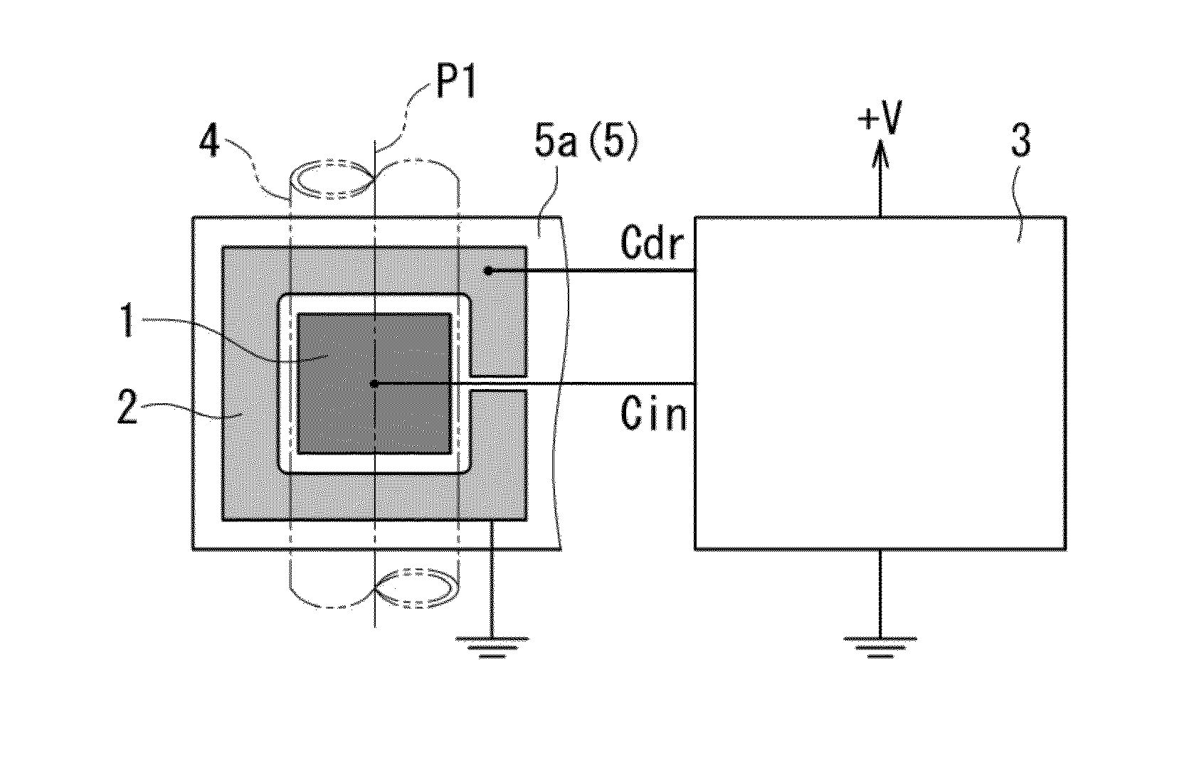
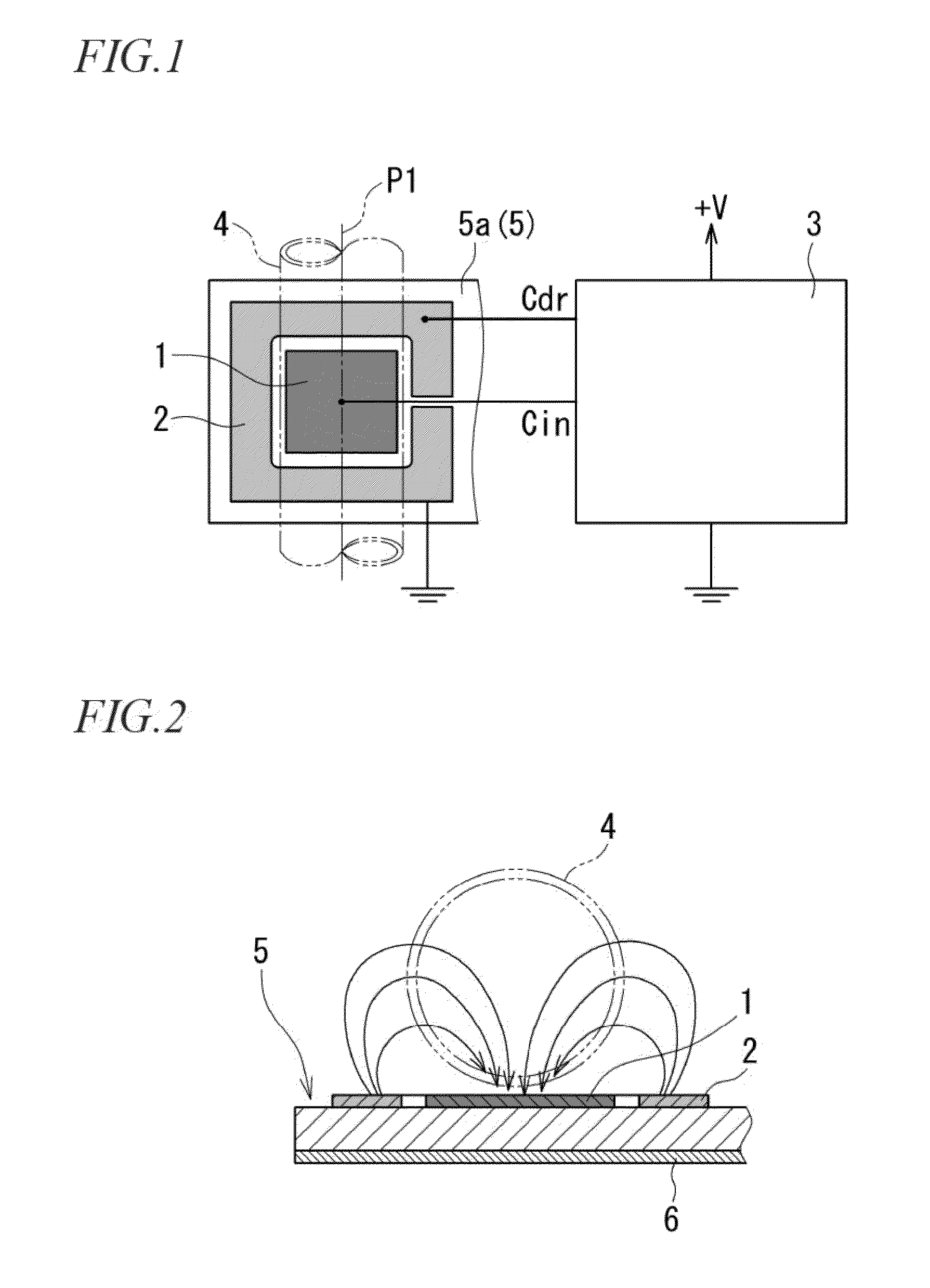
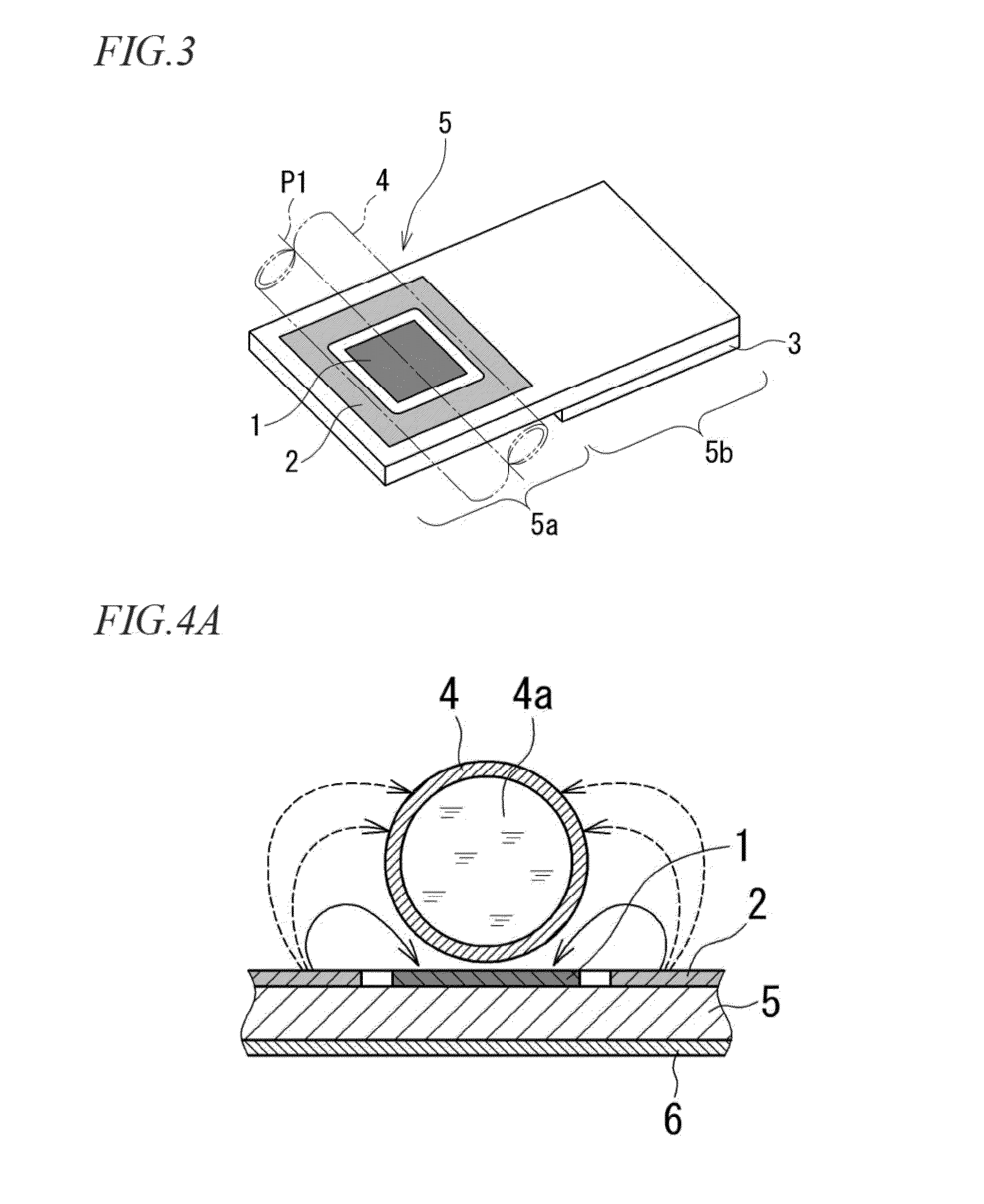
[0027]FIG. 1 is a block diagram of a detection device according to the present invention. FIG. 2 is a cross-sectional diagram of the detection device, and FIG. 3 is a schematic perspective view of the detection device.

[0028]As shown in FIGS. 1 to 3, the detection device is provided with a detection electrode 1, a drive electrode 2, and a controller 3, and detects the state of a tubular body 4 which is positioned at a predefined specified position P1, and that is in the vicinity of the detection electrode 1. The specified position P1 is set to be in a three-dimensional space as described later. In FIGS. 1 and 3, the center position of the specified position P1 is shown by a single-dot chain line labeled PL and an outline of the tubular body 4 is shown by a double-dot chain line.

[0029]The detection electrode 1 is placed in a sensor region 5a on a surface of a sensor board 5 which is made of an insulator. The drive electrode 2 is placed on the same plane (on the same plane or on the sa...

seventh embodiment

[0059]FIG. 10 is a schematic perspective view of the detection device of the invention, and FIG. 11 is a cross-sectional diagram of main portions of the embodiment.

[0060]In the seventh embodiment, the sensor board 5 is covered by a cover so as to sandwich the detection electrode 1 and the drive electrode 2. In the illustrated example, the whole surface of the sensor board 5 including the sensor region 5a of the sensor board 5 where the detection electrode 1 and the drive electrode 2 are placed is covered by a resin made cover 10.

[0061]According to the seventh embodiment, as seen in FIG. 11, the transfusion tube (tubular body) 4 is used in a state where it is placed on the resin made cover 10, and therefore cleaning, is further facilitated. As seen from FIGS. 10 and 11, the detection electrode 1 and the chive electrode 2 are covered by the resin made cover 10. Therefore, a short circuit can be prevented from occurring caused by penetration of liquid such as leaking transfusion into t...


PUM

PropertyMeasurementUnit
electric forceaaaaaaaaaa
diameteraaaaaaaaaa
flexibleaaaaaaaaaa

Abstract

There is provided a detection device including: a detection electrode that is arranged at a position on an arrangement plane near a tubular body a drive electrode that is arranged on the arrangement plane; and a controller configured to generate lines of electric force between the detection electrode and the drive electrode and to detect a state of the tubular body by detecting lines of electric force entering the detection electrode.

Description

BACKGROUND OF THE INVENTION[0001]1. Field of the Invention The present invention relates to a detection device which detects a state of a tubular body. Examples of such state are: presence or absence of a tubular body at a specified position type of diameter (inside diameter, outside diameter, and wall thickness) of the tubular body; presence or absence of a fluid such as liquid flowing through the tubular body; the type of the fluid, in particular liquids; presence or absence of an air bubble in a liquid; and state related to the tubular body at the specified position and to a fluid, in particular liquid, flowing through the tubular body.[0002]2. Description of the Related Art[0003]Conventionally, the devices disclosed in JP-A-2012-205866 and JP-A-2007-296134 have been developed as a detection device of this kind, particularly, a detection. device for detecting an air bubble in liquid such as a medical solution or dialysis solution flowing through a transfusion tube (tubular body)....

Claims


Application Information

Patent Timeline
Patent Type & Authority Applications(United States)
IPC IPC(8): G01R1/06G01N27/02
CPCG01N27/02G01R1/06G01N27/04G01N27/041G01N27/06G01N27/20G01N27/60
Inventor MUTO, AKIRAOBATA, YASUTOSHIOHMAE, HIROYUKIOMORI, KIYOSHIISHII, YOHEI
Owner MINEBEAMITSUMI INC
Why Eureka
Try Eureka