
Image stabilization apparatus, lens apparatus, and imaging apparatus

a technology of image stabilization and lens, applied in the field of image stabilization apparatus, can solve the problems of reducing the corrective accuracy, the negative influence of the corrective lens unit on the other corrective lens through magnetic interference, etc., and achieve the effect of restrainting the degraded corrective accuracy and reducing the magnetic interferen

Active Publication Date: 2019-03-26
CANON KK
View PDF15 Cites 4 Cited by
  • Summary
  • Abstract
  • Description
  • Claims
  • Application Information

AI Technical Summary

Benefits of technology

The patent describes an invention that reduces the interference between different corrective lens units and helps to improve the accuracy of the correction. This invention can be used in image stabilization apparatuses, lens apparatuses, and imaging apparatuses.

Problems solved by technology

However, as the distances among the plurality of corrective lens units reduce, a leak magnetic flux from a magnet that drives one corrective lens unit negatively affects another corrective lens through a magnetic interference.
As a result, the correcting accuracy may lower.

Method used


Image

  • Image stabilization apparatus, lens apparatus, and imaging apparatus
  • Image stabilization apparatus, lens apparatus, and imaging apparatus
  • Image stabilization apparatus, lens apparatus, and imaging apparatus

Examples


Embodiment Construction

[0020]Referring now to the accompanying drawings, a detailed description will be given of embodiments according to this embodiment.

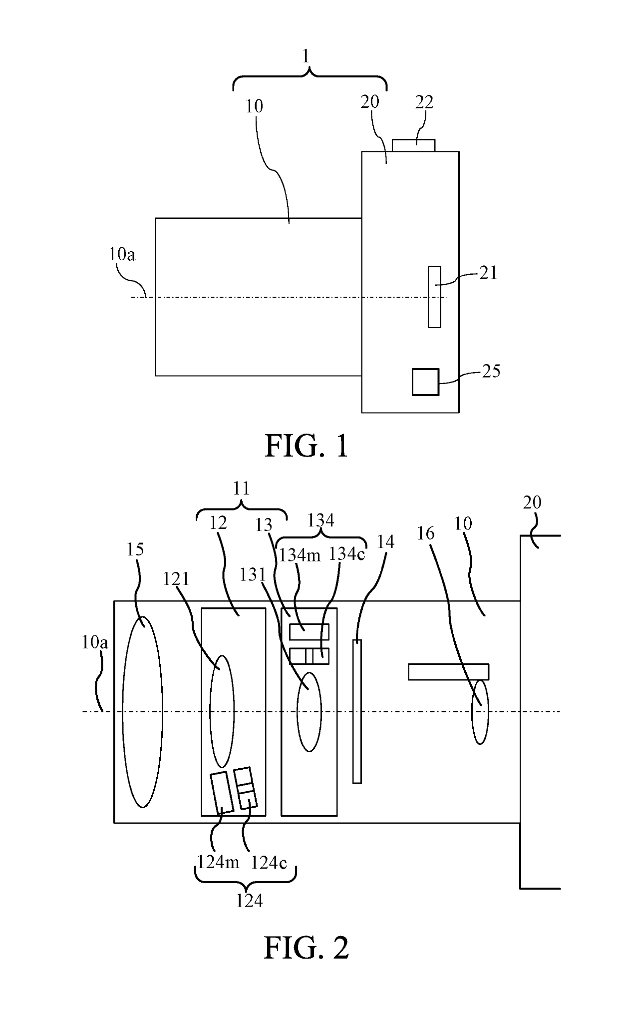
[0021]Referring now to FIG. 1, an outline of an imaging apparatus according to this embodiment will be given. FIG. 1 is a sectional view of an imaging apparatus 1 viewed from its side. In this embodiment, the imaging apparatus 1 includes a camera body 20 (imaging apparatus body), and a lens barrel 10 (interchangeable lens or lens apparatus) attached to and detached from a camera body 20. However, this embodiment is not limited to this example and is applicable to an imaging apparatus in which the lens barrel 10 is integrated with the camera body 20.

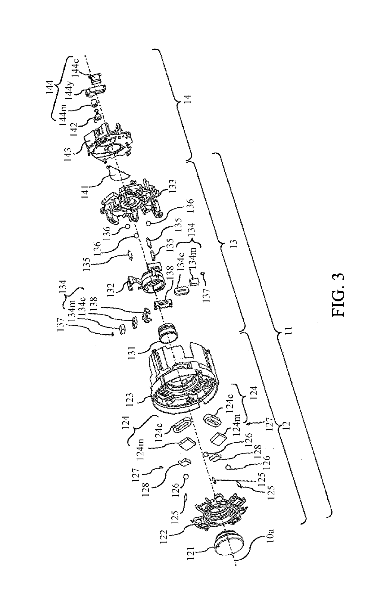
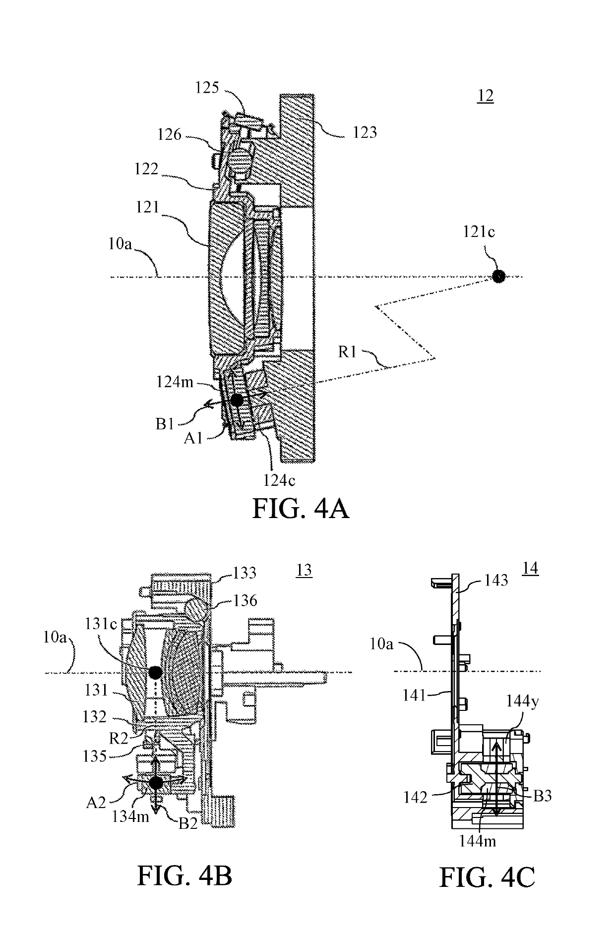
[0022]An optical axis 10a corresponds to a center of an (imaging) optical system in the lens barrel 10. An imaging unit 21 provided in the camera body 20 includes an image sensor (photoelectric converter), such as a CMOS sensor, which photoelectrically converts an optical image (object image) formed by the len...


PUM


Abstract

An image stabilization apparatus includes a first optical element configured to move in a direction different from an optical axis, a first driver including a first magnet magnetized in a first magnetized direction and a first coil and configured to drive the first optical element by an electromagnetic action, a second optical element configured to move in a direction different from the optical axis, and a second driver including a second magnet magnetized in a second magnetized direction and a second coil and configured to drive the second optical element by an electromagnetic action. The first magnet is disposed outside a second area onto which the second magnet is projected in the second magnetized direction and the second magnet is disposed outside a first area onto which the first magnet is projected in the first magnetized direction.

Description

BACKGROUND OF THE INVENTIONField of the Invention[0001]The present invention relates to an image stabilization apparatus that reduces an image blue caused by a hand shake, etc.Description of the Related Art[0002]The image stabilization apparatus has been conventionally known and reduces an image blur by moving the entire or part of the optical system in a direction orthogonal to an optical axis. The image stabilization apparatus is demanded to significantly move the optical system in order to correct a large image blur. Japanese Patent Laid-Open No. (“JP”) 2015-125246 discloses a zoom lens that corrects a large image blur without degrading the optical performance through a shift correction and a tilt correction for the image blur correction with a plurality of corrective lens units.[0003]In the zoom lens disclosed in JP 2015-125246, distances among the plurality of corrective lens units for an image stabilization may be small depending on situations. Usually, the corrective lens uni...

Claims


Application Information

Patent Timeline
Patent Type & Authority Patents(United States)
IPC IPC(8): G02B27/64G02B7/02H04N5/232
CPCG02B27/646H04N5/2328G02B7/021H04N23/685
Inventor IZUMI, MITSUHIROOCHI, YOUJIUEMURA, KOHEIMIYOSHI, KAORI
Owner CANON KK
Learn More