
High voltage circuit breaker

a high-voltage circuit and circuit breaker technology, applied in the direction of protective switch operating/release mechanism, protective switch details, protective switch terminal/connection, etc., can solve the problems of increasing the weight of the overall circuit breaker assembly, mechanical stability problems, and increasing the complexity of the electrical system, so as to achieve light weight and less complex

Inactive Publication Date: 2019-03-26
SIEMENS ENERGY GLOBAL GMBH & CO KG
View PDF12 Cites 0 Cited by
  • Summary
  • Abstract
  • Description
  • Claims
  • Application Information

AI Technical Summary

Benefits of technology

The improved design results in a lighter, easier-to-assemble, and more stable circuit breaker with reduced seismic risk, requiring less material and assembly time, while maintaining efficient current flow management and protection against over-voltage transients.

Problems solved by technology

Hence, the electrical systems are becoming increasingly complex, heavy, and powerful.
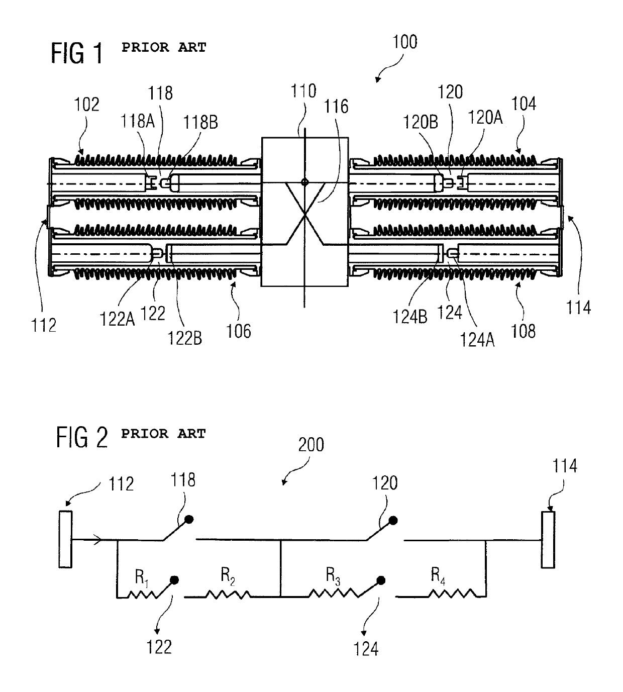
The high voltage circuit breaker 100, illustrated in FIG. 1 and FIG. 2, needs a good amount of material for manufacturing due to the presence of multiple closing resistor units, which also increases the weight of the overall circuit breaker assembly.
Due to high weight of the circuit breaker, it becomes problematic to keep the circuit breaker at an elevated height and it causes mechanical stability problems.
Also, the time required to assemble the high voltage circuit breaker is also high because of the complexity of the circuit breaker due to the presence of multiple closing resistor units.
Additionally, the circuit breaker, as disclosed in the state of the art, is susceptible to high risk of failure due to seismic load because of its complex design and weight.
Further, due to the presence of multiple main and resistor contacts, high mechanical energy is required for operating the contacts because more number of contacts leads to more number of moving parts.

Method used


Image

  • High voltage circuit breaker
  • High voltage circuit breaker
  • High voltage circuit breaker

Examples


Embodiment Construction

[0027]Various embodiments are described with reference to the drawings, wherein like reference numerals are used to refer to like elements throughout. In the following description, for purpose of explanation, numerous specific details are set forth in order to provide a thorough understanding of one or more embodiments. It may be evident that such embodiments may be practiced without these specific details.

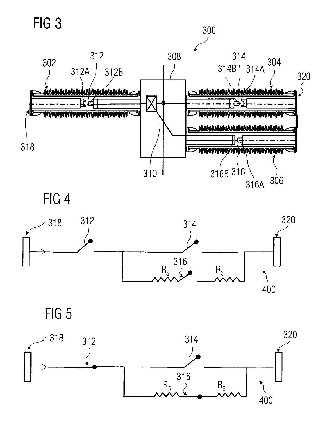
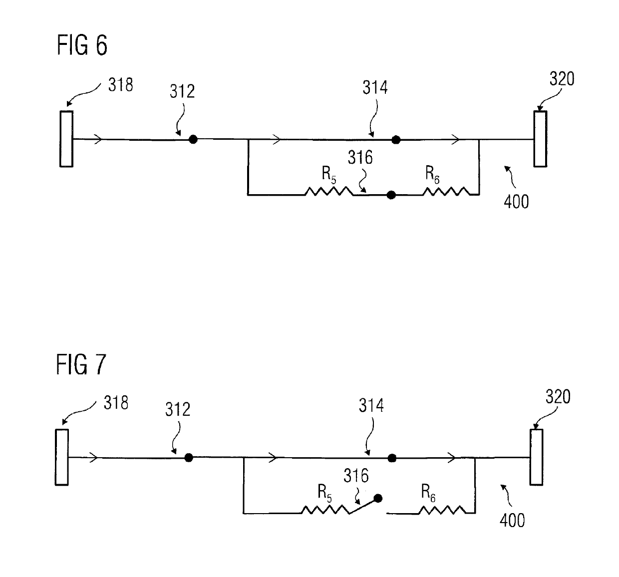
[0028]FIG. 3 illustrates an improved circuit breaker 300 in accordance with an embodiment. The improved circuit breaker 300 includes two interrupter units 302, 304 and a closing resistor unit 306. The improved circuit breaker 300 also includes a breaker tank 308, an incoming terminal 318, and an outgoing terminal 320. The breaker tank 308 including mechanical links 310, as illustrated in FIG. 3. During normal operation, current is flowing through the improved circuit breaker 300 from the incoming terminal 318 to the outgoing terminal 320 through the incoming interrupter unit 302 a...


PUM


Abstract

An improved circuit breaker is disclosed herein. The improved circuit breaker includes one or more main contacts and only one resistor contact. The only one resistor contact is connected in parallel with at least one of the one or more main contacts.

Description

[0001]The present patent document is a § 371 nationalization of PCT Application Serial Number PCT / EP2016 / 050680, filed Jan. 14, 2016, designating the United States, which is hereby incorporated by reference, and this patent document also claims the benefit of Indian Patent Application Number IN 63 / KOL / 2015, filed Jan. 19, 2015, which is also hereby incorporated by reference.TECHNICAL FIELD[0002]The present disclosure relates to a high voltage circuit breaker and more particularly, to a new arrangement of closing resistors in an extra high voltage circuit breaker.BACKGROUND[0003]From the last few decades, there is a continuous increase in the demand of electrical power for various residential and industrial applications. Hence, the electrical systems are becoming increasingly complex, heavy, and powerful. A requirement of a high voltage electrical system is high voltage switching equipment. The high voltage switching equipment are used to control, protect and isolate electrical modul...

Claims


Application Information

Patent Timeline
Patent Type & Authority Patents(United States)
IPC IPC(8): H01H71/10H01H9/54H01H71/08H01H33/16H01H71/02
CPCH01H71/10H01H33/168H01H71/08H01H71/02H01H9/54H01H33/16
Inventor GOPA, SRINIVASRICHTER, FRANKSHENDE, AMITTEICHMANN, JORG
Owner SIEMENS ENERGY GLOBAL GMBH & CO KG
Learn More