Fuel cell separator
a fuel cell and separator technology, applied in the field of separators, can solve the problems of lack of strength at weld parts, extreme deterioration of moldability, lack of uniformity, etc., and achieve the effects of reducing resistivity, stable dimension, and high gas tightness
- Summary
- Abstract
- Description
- Claims
- Application Information
AI Technical Summary
Benefits of technology
Problems solved by technology
Method used
Image
Examples
embodiment 1
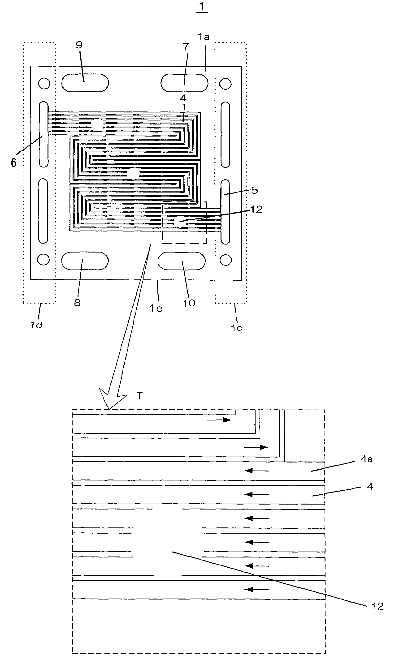
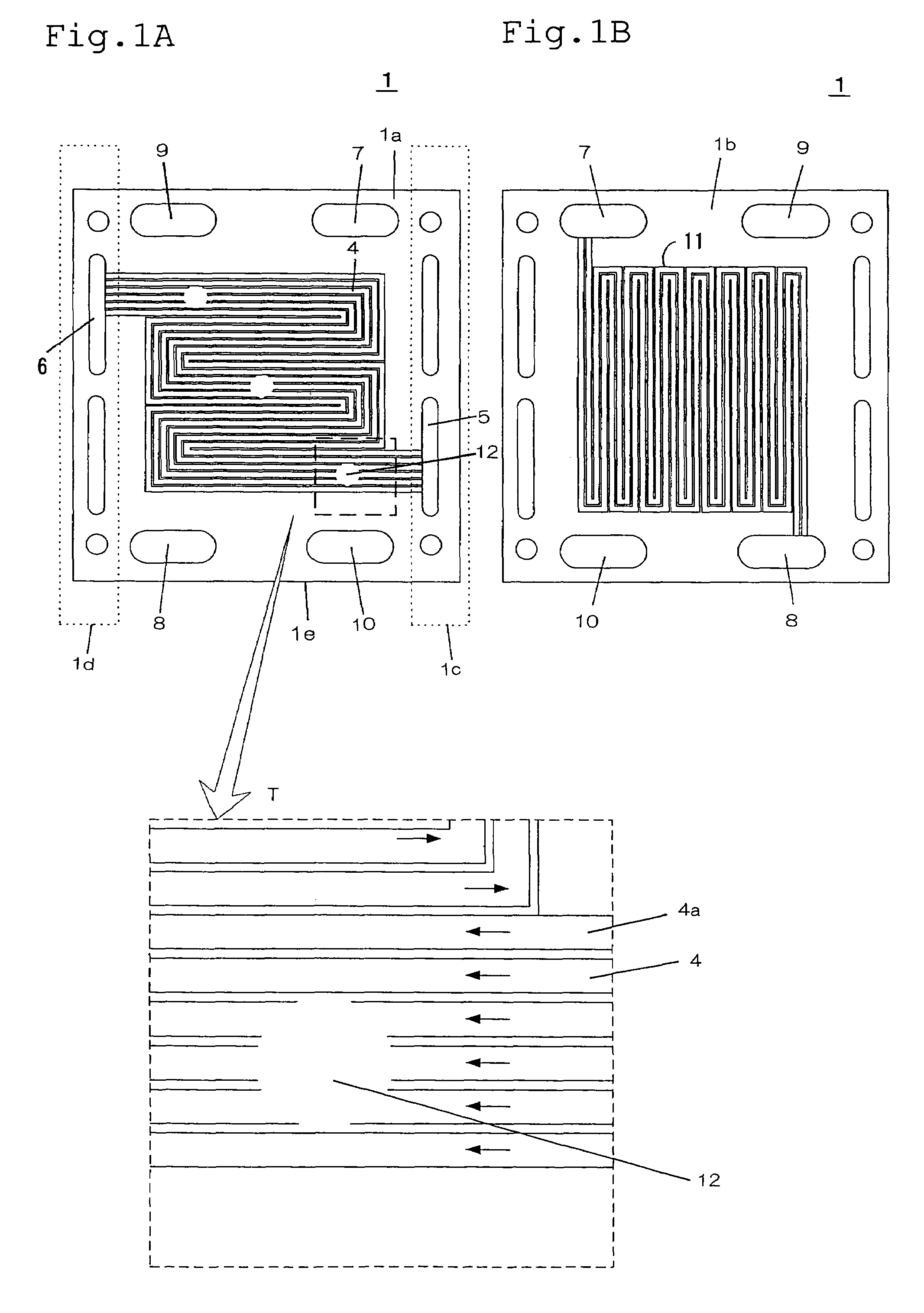
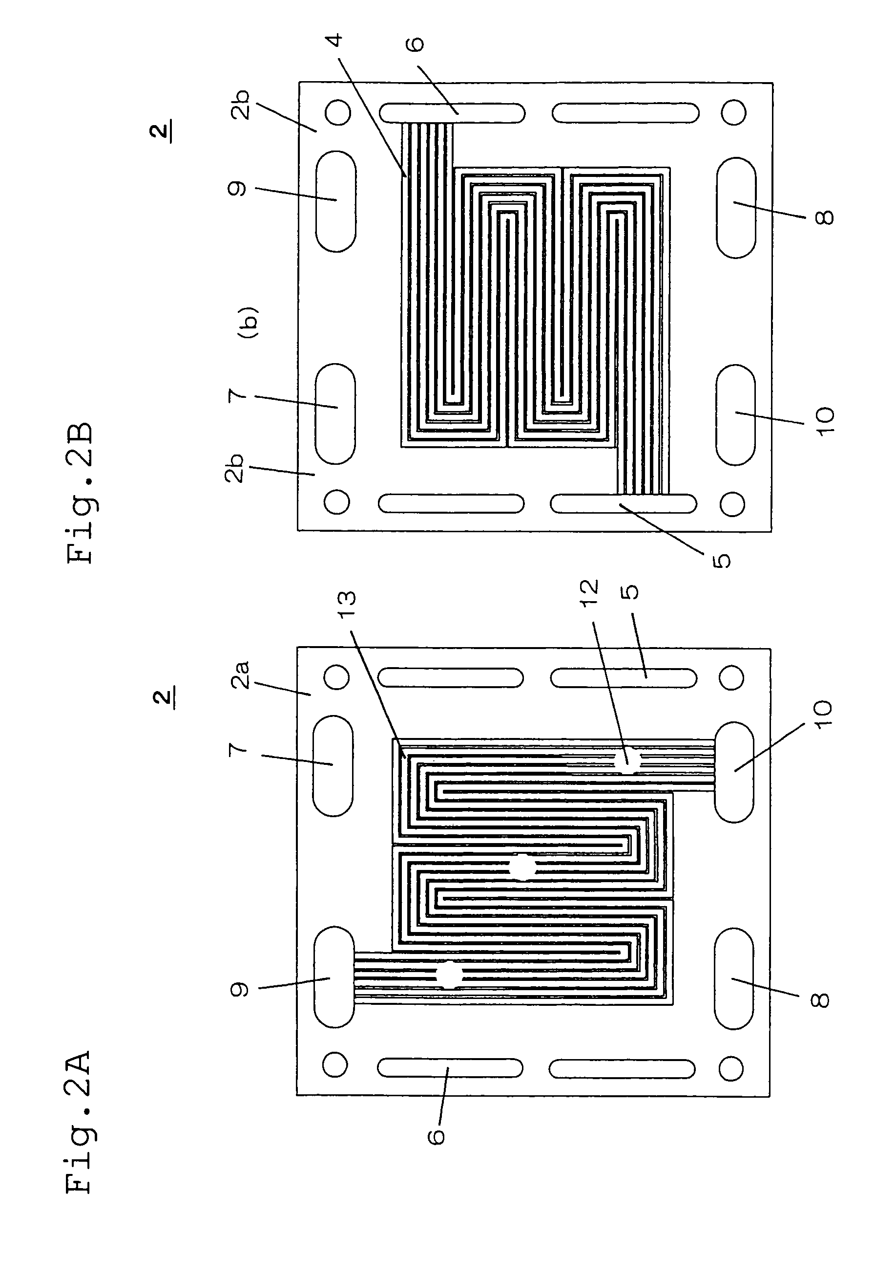
[0105]The configuration of a separator according to the Embodiment 1 of implementation of the invention will be described below. FIGS. 1 to 3 are a plan view of three fuel cell separators according to the Embodiment 1 of implementation of the invention, respectively. FIG. 1A is a plan view of the side 1a of a separator (W / A) 1 on which a cooling medium flow path is formed. FIG. 1B is a plan view of the side 1b of the separator (W / A) 1 on which a fuel gas flow path is formed.
[0106]As shown in FIG. 1A, the separator (W / A) 1 according to the Embodiment 1 of implementation of the invention has a cooling medium flow path 4 provided on the side 1a thereof. A cooling water inlet manifold 5 through which cooling water is supplied into the cooling medium flow path 4 and a cooling water outlet manifold 6 through which cooling water is discharged are formed around the cooling medium flow path 4 and along the edge of the separator (W / A) 1. The cooling water inlet manifold 5 and the cooling wate...
embodiment 2
[0254]Another embodiment will be described below. As the elements other than separator there were used the same elements as used in the Embodiment 1 of implementation of the invention. Evaluation was conducted in the following manner.
[0255]In the Embodiment 2 of implementation of the invention, too, as the compound for electrically-conductive site there was used a 7:3 mixture (by weight) of graphite and PPS (polyphenylene sulfide) resin as used in the Embodiment 1 of implementation of the invention. Molding was then conducted in such an arrangement that the molding material injection gate marks 12 to be formed on the flow path were formed in the positions as set forth in Table 3.
[0256]The injection molding machine used was the same as used in the Embodiment 1 of implementation of the invention except the injection pressure. The various separators thus prepared were each subjected to cell test in the same manner as in the Embodiment 1 of implementation of the invention. The configura...
PUM
| Property | Measurement | Unit |
|---|---|---|
| heat resistance | aaaaa | aaaaa |
| temperature | aaaaa | aaaaa |
| particle diameter | aaaaa | aaaaa |
Abstract
Description
Claims
Application Information
 - R&D
- Intellectual Property
- Life Sciences
- Materials
- Tech Scout
- Unparalleled Data Quality
- Higher Quality Content
- 60% Fewer Hallucinations
Browse by: Latest US Patents, China's latest patents, Technical Efficacy Thesaurus, Application Domain, Technology Topic, Popular Technical Reports.
© 2025 PatSnap. All rights reserved.Legal|Privacy policy|Modern Slavery Act Transparency Statement|Sitemap|About US| Contact US: help@patsnap.com


