Lidar system including holographic imaging optics

Pending Publication Date: 2021-12-16
ROBERT BOSCH GMBH
View PDF0 Cites 0 Cited by
  • Summary
  • Abstract
  • Description
  • Claims
  • Application Information

AI Technical Summary

Benefits of technology

[0004]It is an object of the present invention to reduce the number of detectors necessary for detecting the 3D point cloud. This object may be achieved by a LIDAR

Problems solved by technology

Otherwise, the laser light reflected by an object would be difficult to distinguish from the background radiation, in particular, in the case of direct solar radiation.
However, the plurality of detectors necessary for this purpose has the disadvantage that in this way the co

Method used


Image

  • Lidar system including holographic imaging optics
  • Lidar system including holographic imaging optics
  • Lidar system including holographic imaging optics

Examples


Embodiment Construction

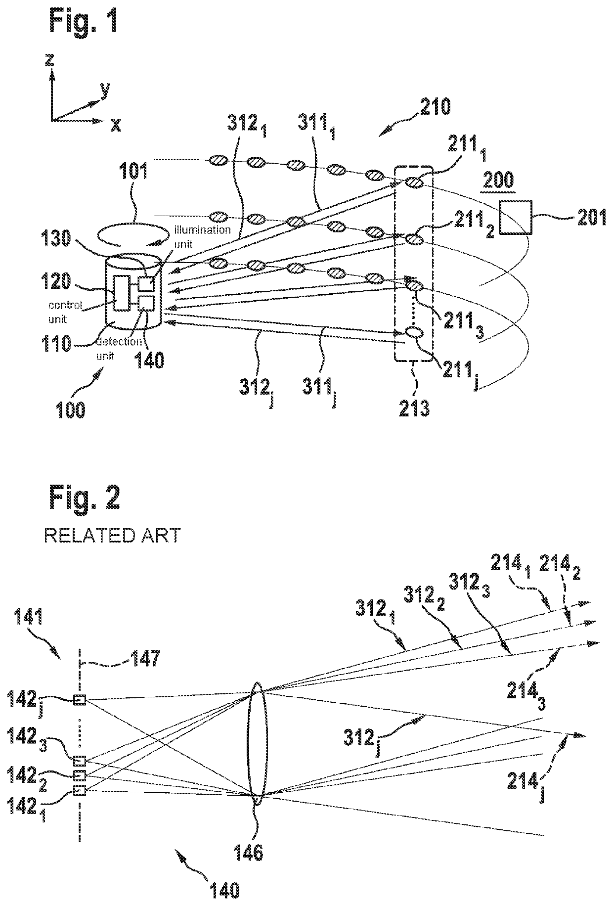
[0025]FIG. 1 schematically illustrates the principle of a scanning

[0026]LIDAR system 100, which scans a defined observation area 210 of its immediate surroundings 200 with the aid of light beams 311j.

[0027]LIDAR system 100 includes an illumination unit 130, which is situated in a rotating housing 110 and includes multiple photoemitters for generating one or multiple light radiation(s), which is / are emitted in the form of separate light or laser beams 311j into different spatial directions. In the process, each of light beams 311j illuminates a spatial area 211j which is individually assigned to the particular light beam 311j, in the present example spatial areas 211j detected simultaneously by illumination unit 130 at a certain point in time being situated vertically beneath one another, so that the present field of view 213 of LIDAR system 100 forms a more or less coherent strip. Housing 110 and illumination unit 130 situated therein are pivoted along a predefined scanning directio...


PUM


Abstract

A LIDAR system for detecting objects within an observation area. The LIDAR system includes an illumination unit for illuminating the observation area using multiple light radiations, each having a different wavelength, multiple separate spatial areas of the observation area, which are presently detected by a detection area of the LIDAR system, being temporally consecutively illuminated in each case with another of the light radiations; and a detection unit for detecting the light radiations reflected by objects, including at least one detection array, which is individually assigned to the particular detection area and is made of up of a detector for detecting the light radiations from the spatial areas presently detected by the detection area, and a holographic imaging optics for focusing the respective light radiations onto the detector.

Description

FIELD[0001]The present invention relates to a LIDAR system including a holographic imaging optics. The present invention furthermore relates to a holographic imaging optics for such a LIDAR system.BACKGROUND INFORMATION[0002]LIDAR systems are used for ascertaining 3D data of an observation area. Such a system includes at least one photoemitter for generating light radiation of certain wavelengths, which is typically designed in the form of a laser, and at least one detector for detecting light radiation of the respective wavelengths. During operation of the system, the light radiation which is emitted by the emitter and reflected or scattered on objects in the observation area is detected by the detector. By measuring the runtimes of the light radiation reflected on the scanned objects, it is possible to calculate the distance of the particular objects. Typical LIDAR systems carry out a plurality of individual measurements in the observation area, during each of which only a small s...

Claims


Application Information

Patent Timeline
IPC IPC(8): G01S17/89G01S7/481G02B5/32G03H1/02
CPCG01S17/89G01S7/4816G03H1/0248G01S7/4817G02B5/32G01S7/4815G01S17/42G01S7/4814G02B26/106
Inventor RAMSTEINER, INGOFIESS, REINHOLD
Owner ROBERT BOSCH GMBH
Why Eureka
Try Eureka