Managing link aggregation traffic in edge nodes

a technology of link aggregation and edge node, applied in data switching networks, instruments, high-level techniques, etc., can solve problems such as complicated load balancing between network edge nodes

Active Publication Date: 2019-03-26
NICIRA
View PDF61 Cites 0 Cited by
  • Summary
  • Abstract
  • Description
  • Claims
  • Application Information

AI Technical Summary

Problems solved by technology

Load balancing between network edge nodes, however, is complicated by the mapping of data link layer addresses to each edge node and by the handling of packets that are destined for a specific network edge node but received by another network edge node.

Method used


Image

  • Managing link aggregation traffic in edge nodes
  • Managing link aggregation traffic in edge nodes
  • Managing link aggregation traffic in edge nodes

Examples


Embodiment Construction

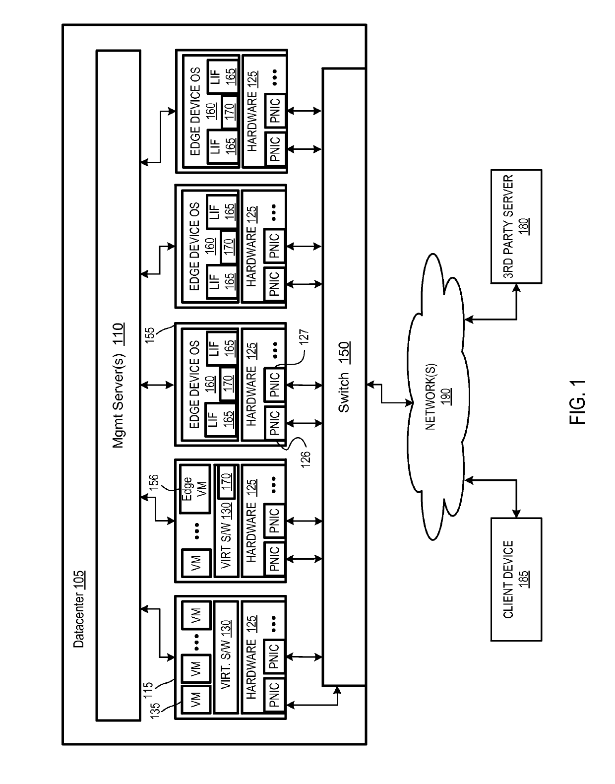
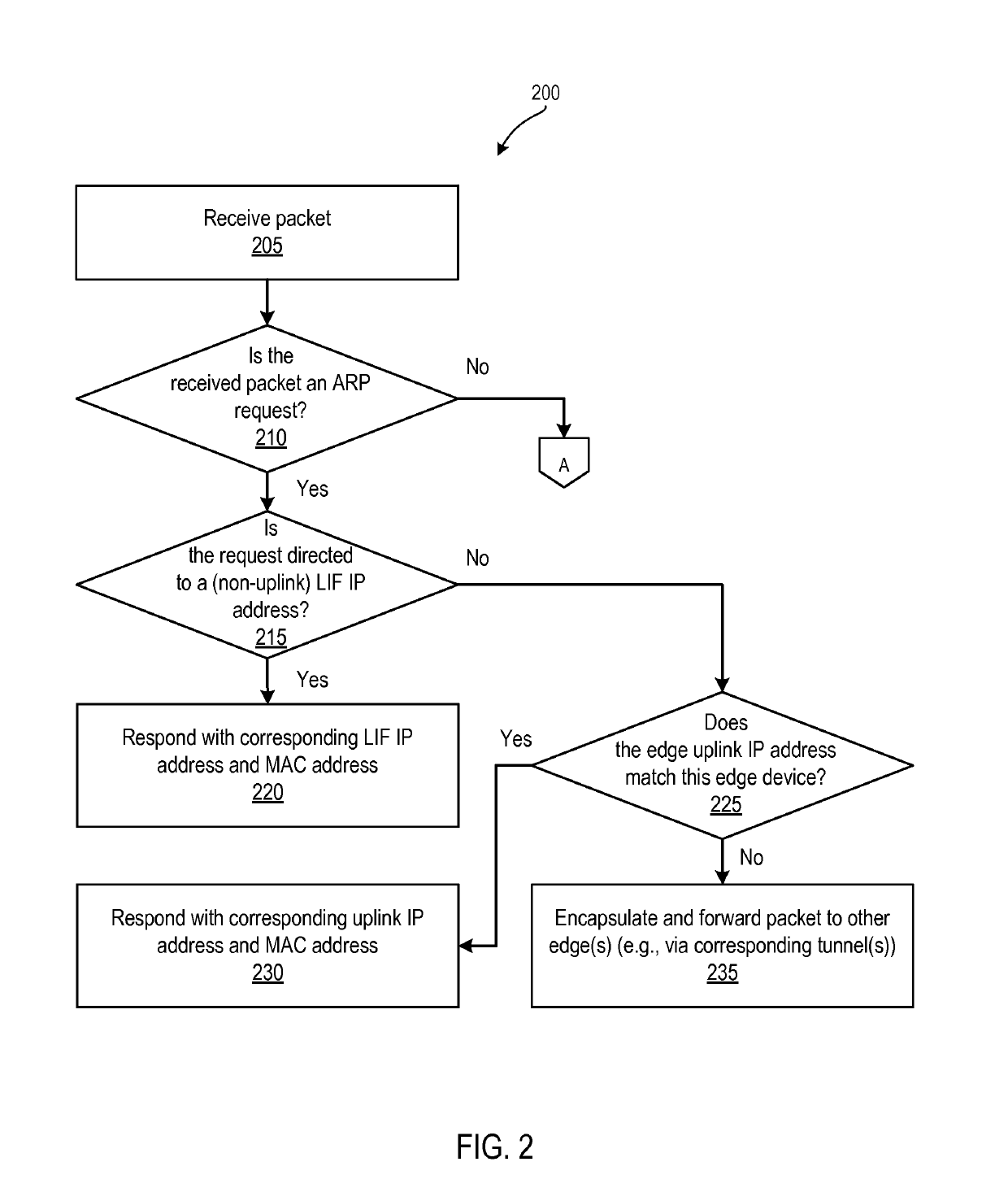
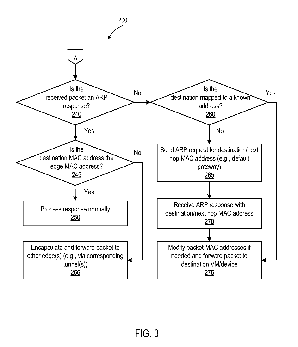
[0008]Embodiments described herein balance traffic among and manage traffic between network edge devices. In particular, embodiments configure a mapping between a physical network interface of a first network device and a plurality of logical interfaces within the first network device. One or more additional network devices also configure a mapping between a corresponding physical network interface and a copy of the plurality of logical interfaces within the corresponding network device. Each of the logical interfaces is assigned a set of first and second layer networking addresses (e.g., addresses for layers 3 and 2 in the OSI model) that is replicated across the network edge devices. The replicated logical interfaces will therefore share the same data link layer (e.g., MAC) address. For example, each logical interface may serve as a default gateway for a different subnet of VMs or other networked machines. As a result, each edge device is able to process packets directed to any of...


PUM


Abstract

Exemplary methods, apparatuses, and systems include a first network edge device configuring a mapping between a physical network interface and a plurality of logical interfaces. A second network edge device also configures a mapping between a physical network interface and a copy of the plurality of logical interfaces. Each of the logical interfaces is assigned a corresponding set of first and second layer networking addresses that is replicated across the first and second network edge devices. The first network edge device receives a first address resolution request via the physical network interface of the first network edge device that includes a source and a destination. The destination is an address assigned to one of the plurality of logical interfaces. The first network edge device determines a second layer networking address assigned to the destination logical interface and transmits an address resolution response including the determined second layer networking address.

Description

FIELD OF THE INVENTION[0001]The various embodiments described herein relate to managing link aggregation traffic in a virtual environment. In particular, the embodiments relate to using a link aggregation group to implement load balancing of data link layer processing between multiple network edge devices or other network edge nodes.BACKGROUND OF THE INVENTION[0002]Load balancing distributes workload across multiple physical or virtual machines. In a datacenter environment, a load balancer may be implemented using link aggregation. For example, multiple physical and / or virtual machines may serve as a network edge node, such as a gateway or router. As each packet is received, one of multiple network edge nodes is selected to process the packet as a result of each network edge node having a physical network interface / port included within a common link aggregation group. Load balancing between network edges distributes the work of network layer packet processing and, as a result, incre...

Claims


Application Information

Patent Timeline
Patent Type & Authority Patents(United States)
IPC IPC(8): H04L29/12H04L12/709G06F9/455H04L12/803H04L12/741H04L12/931H04L45/243H04L45/74
CPCH04L61/103G06F9/45558H04L45/245H04L47/125Y02D50/30G06F2009/45595H04L45/74H04L49/70Y02D30/50
Inventor RAVINOOTHALA, SREERAM
Owner NICIRA
Why Eureka
Try Eureka