
Enhanced mobility and address resolution in a wireless premises based network

a wireless premises and address resolution technology, applied in the field of premises based wireless networks, can solve the problems of degrading the performance of wired or wireless networks, affecting the performance of wireless networks,

Inactive Publication Date: 2005-02-03
MEIER ROBERT C
View PDF7 Cites 57 Cited by
  • Summary
  • Abstract
  • Description
  • Claims
  • Application Information

AI Technical Summary

Benefits of technology

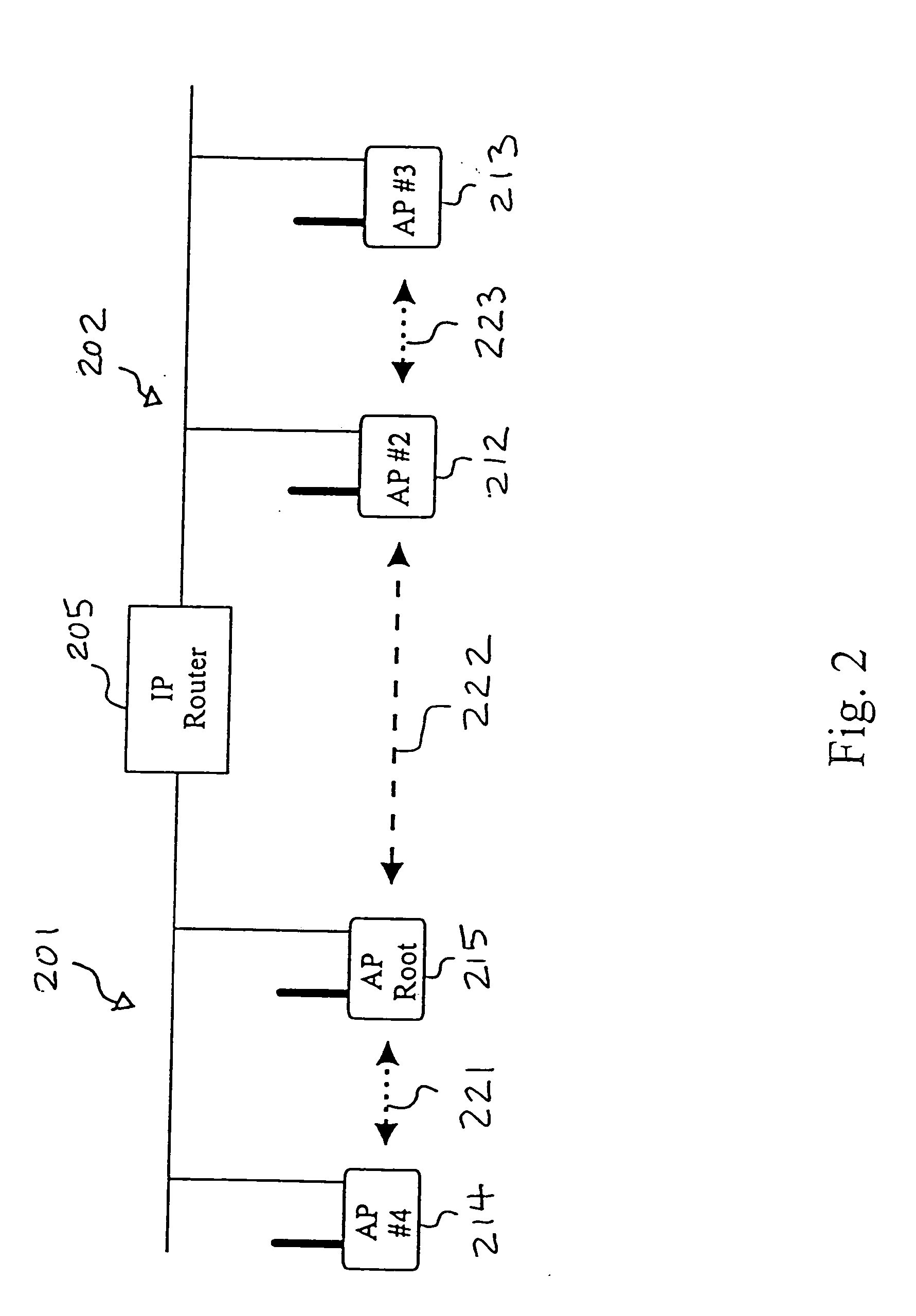
[0009] Additional functionality is provided through the use of data link tunnels that connect access points within a wireless network. The data link tunnels allow passage of data under the wired network protocol to wireless terminals operating under the wired network without extraneous overhead in a communications protocol.

Problems solved by technology

Thus, it is often difficult to merge wired and wireless networks together without degrading performance on either the wired or wireless network.
However, higher level protocols operating in the wired networks often create problems for the wireless networks, especially in those wireless networks where terminals frequently roam.
Specifically, when terminals that communicate with a first AP on one IP (internet protocol) segment of a wired LAN (local area network) roam to communicate with a second AP attached to a second IP segment of the wired LAN, ongoing communication may be lost due to the a need to reregister the roaming device on the second IP segment and unregister that device from the first IP segment.
Thus, IP nodes cannot transparently roam to another IP subnet.
Further, because the APs in different IP segments often reside adjacent one another, the roaming terminals frequently move back and forth between the cells, creating significant problems in the network.

Method used


Image

  • Enhanced mobility and address resolution in a wireless premises based network
  • Enhanced mobility and address resolution in a wireless premises based network
  • Enhanced mobility and address resolution in a wireless premises based network

Examples


Embodiment Construction

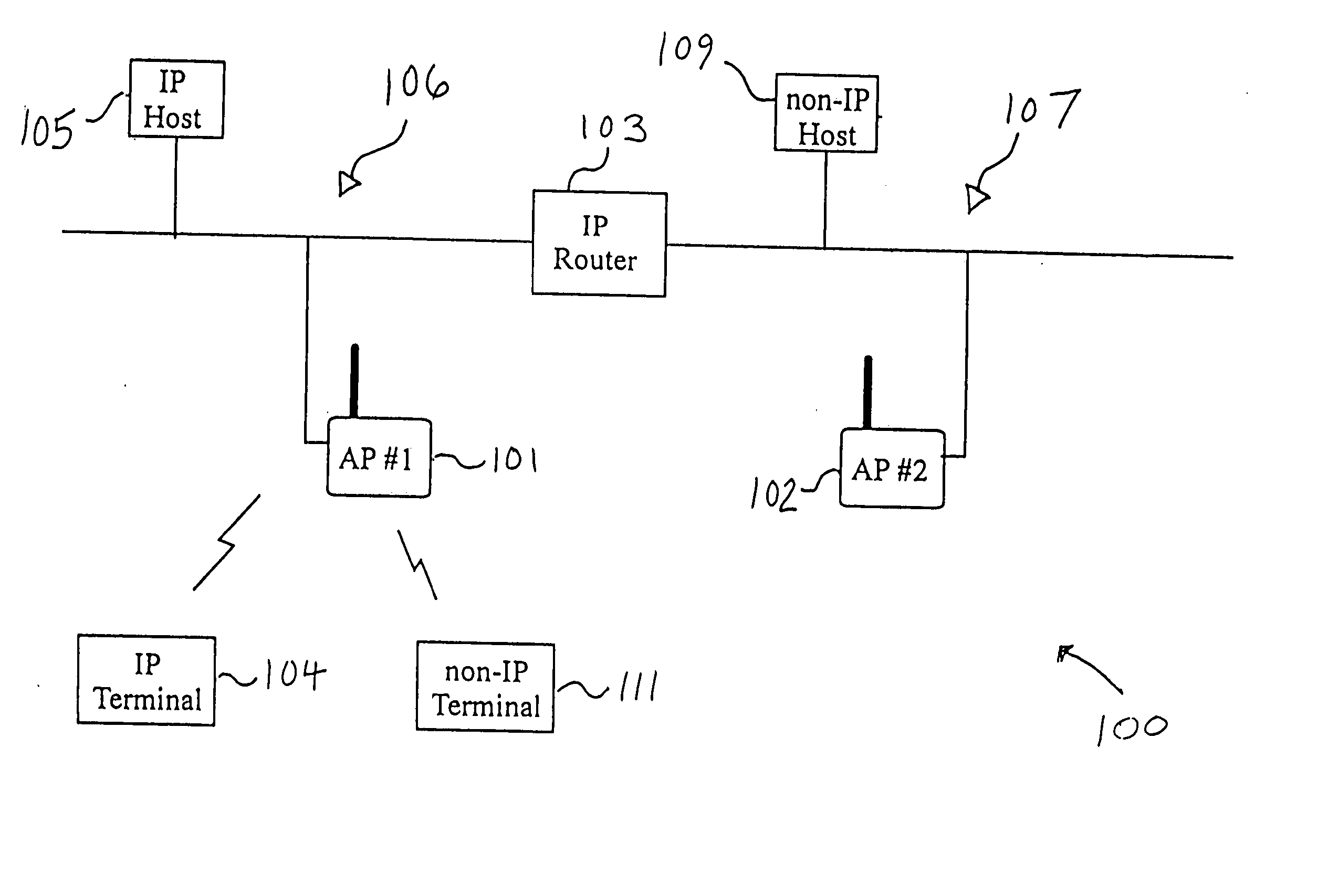
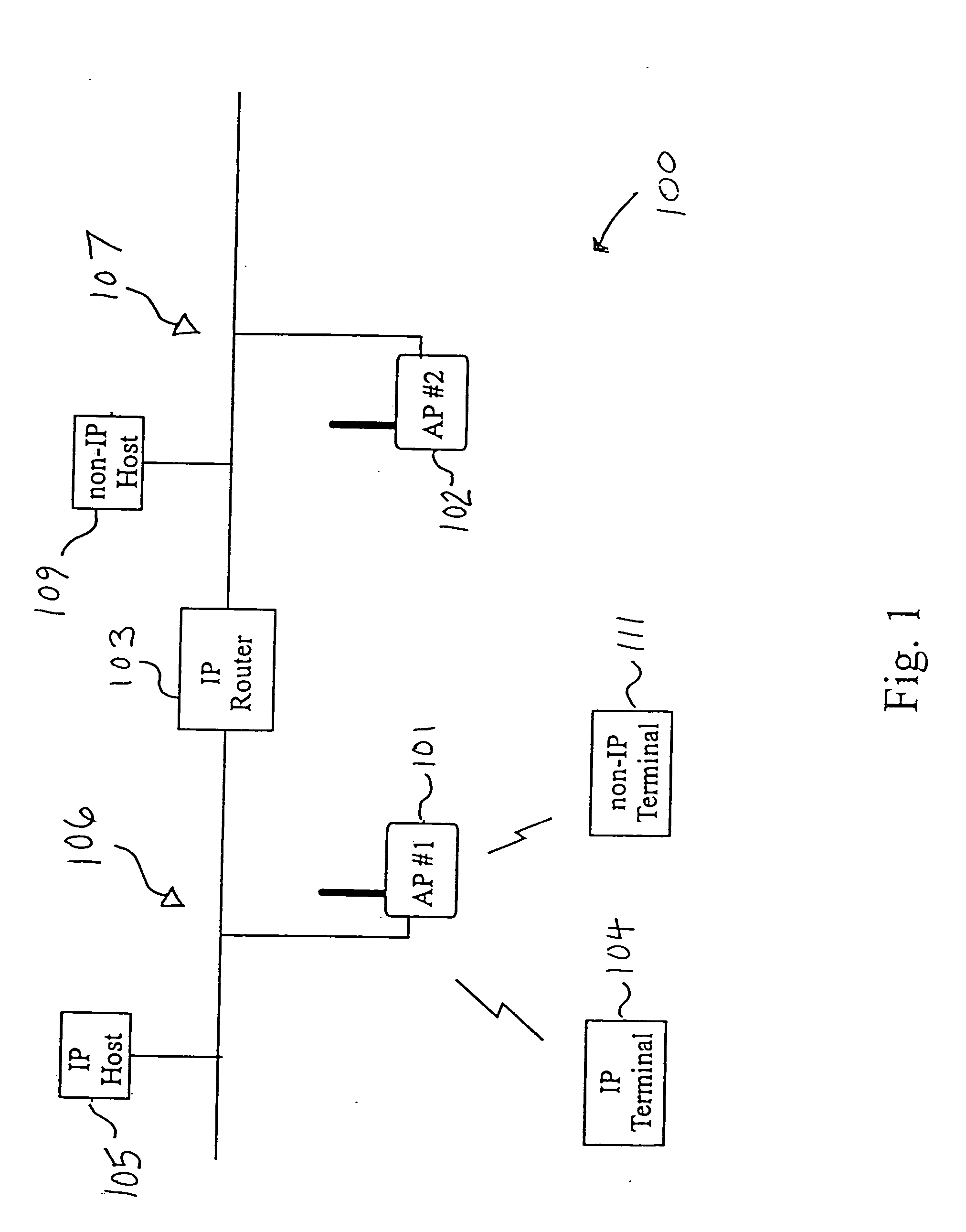
[0022]FIG. 1 is a drawing of an exemplary enterprise network 100 built in accordance with the present invention utilizing tunneling to accommodate migration between IP network segments. An enterprise as used herein refers to a business operation which may be self contained within a single premises or within multiple premises. For example, the enterprise network may be a wired and wireless network used within a single warehouse to support inventory control. It may also include support for mobile, vehicle based communication with such warehouse via a wide area network (“WAN”). Likewise, the enterprise might also include a second warehouse or manufacturing facility located near or remote to the warehouse with wired, satellite or WAN connectivity.

[0023] In particular, within the enterprise network 100 of FIG. 1, the protocols of the present invention, hereinafter referred to as OWL (open wireless local area network) protocols, support a variety of features which enhance mobile or porta...


PUM


Abstract

A premises based wireless network having a multi-segment wired network and a plurality of wireless access points connected to the wired network. The wired network operates according to a wired network protocol which may be the Internet Protocol. Wireless terminals communicate with the wireless access points according to a wireless network protocol, inconsistent with the wired network protocol. Each of the wireless terminals has a wired network address corresponding to one of the wireless access points. Each wireless terminal also has an address according to the wired network protocol. As the wireless terminals roam throughout the premises, protocol tunnels route communications between wireless terminals, thereby preserving communications while roaming by allowing the wireless terminals to retain their wired network addresses during the ongoing communications. The wireless terminals are connected to wireless access points. These wireless access points are in turn linked by data link tunnels to a root access point for a subnet. The data link tunnels enable the root access point for a subnet to forward data to the wireless access points. The forwarded data is not bridged onto the particular subnet that connects the wireless access point and the root access point for that subnet.

Description

CROSS-REFERENCES To RELATED APPLICATIONS [0001] The present case is a continuation of U.S. application Ser. No. 09 / 183,767 filed Oct. 30, 1998, (which is to issue as U.S. Pat. No. 6,701,361 on Mar. 2, 2004), which is a continuation-in-part of U.S. application Ser. No. 08 / 916,601 filed Aug. 22, 1997, which claims the benefit of U.S. Provisional Application No. 60 / 024,648 filed Aug. 22, 1996, and U.S. Provisional Application No. 60 / 043,395 filed Apr. 2, 1997, all of which are hereby incorporated herein by reference in their entirety.BACKGROUND [0002] 1. Technical Field [0003] The present invention relates generally to premises based wireless networks wherein wireless terminals roam between network segments and utilize address resolution techniques for data packet routing purposes; and, more particularly, it relates to techniques for enhancing the mobility of such wireless terminals within the wireless networks while minimizing wireless traffic for address resolution. [0004] 2. Related...

Claims


Application Information

Patent Timeline
Patent Type & Authority Applications(United States)
IPC IPC(8): H04L12/28H04L12/56H04L29/06H04L29/12
CPCH04L29/12009H04L29/12018H04L61/10H04W92/20H04W36/0011H04W80/00H04W80/04H04W8/26H04L61/00H04W36/0019
Inventor MEIER, ROBERT C.
Owner MEIER ROBERT C
Learn More