Connector

a technology of connecting rods and connectors, applied in the direction of coupling contact members, coupling device connections, incorrect coupling prevention, etc., can solve the problem of damage to the end portion of the protruding protrusion b>813/b> in the longitudinal direction, and achieve the effect of high reliability

Active Publication Date: 2019-04-02
MOLEX INC
View PDF6 Cites 12 Cited by
  • Summary
  • Abstract
  • Description
  • Claims
  • Application Information

AI Technical Summary

Benefits of technology

[0011]An object herein is to solve the problem of the conventional connector, and to provide a connector with high reliability that includes rigid reinforcing brackets to be free from displacement and misorientation, and ensures a protected state of housings to be maintained.
[0017]The connector according to the present disclosure can achieve high reliability with a protected state guaranteed for housings with reinforcing brackets being rigid to be free from displacement and misorientation.

Problems solved by technology

As a result, the end portion of the protrusion 813 in the longitudinal direction might be damaged.

Method used


Image

  • Connector
  • Connector
  • Connector

Examples


Embodiment Construction

[0025]Embodiments will be described in detail below with reference to the drawings.

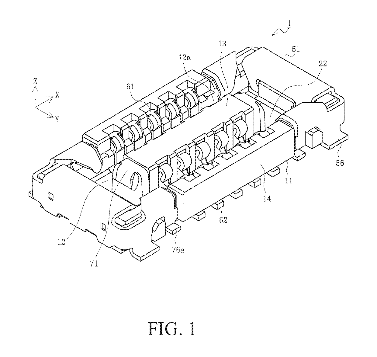
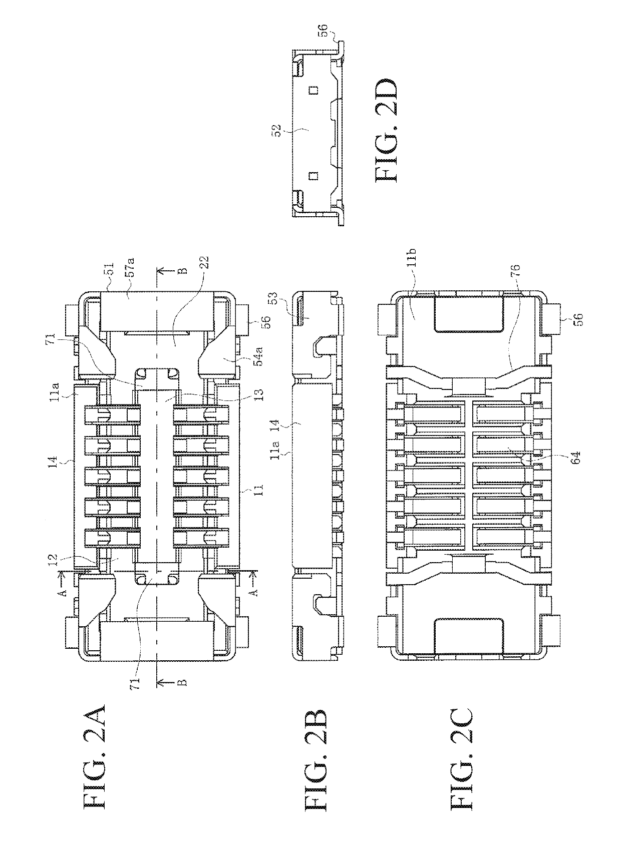
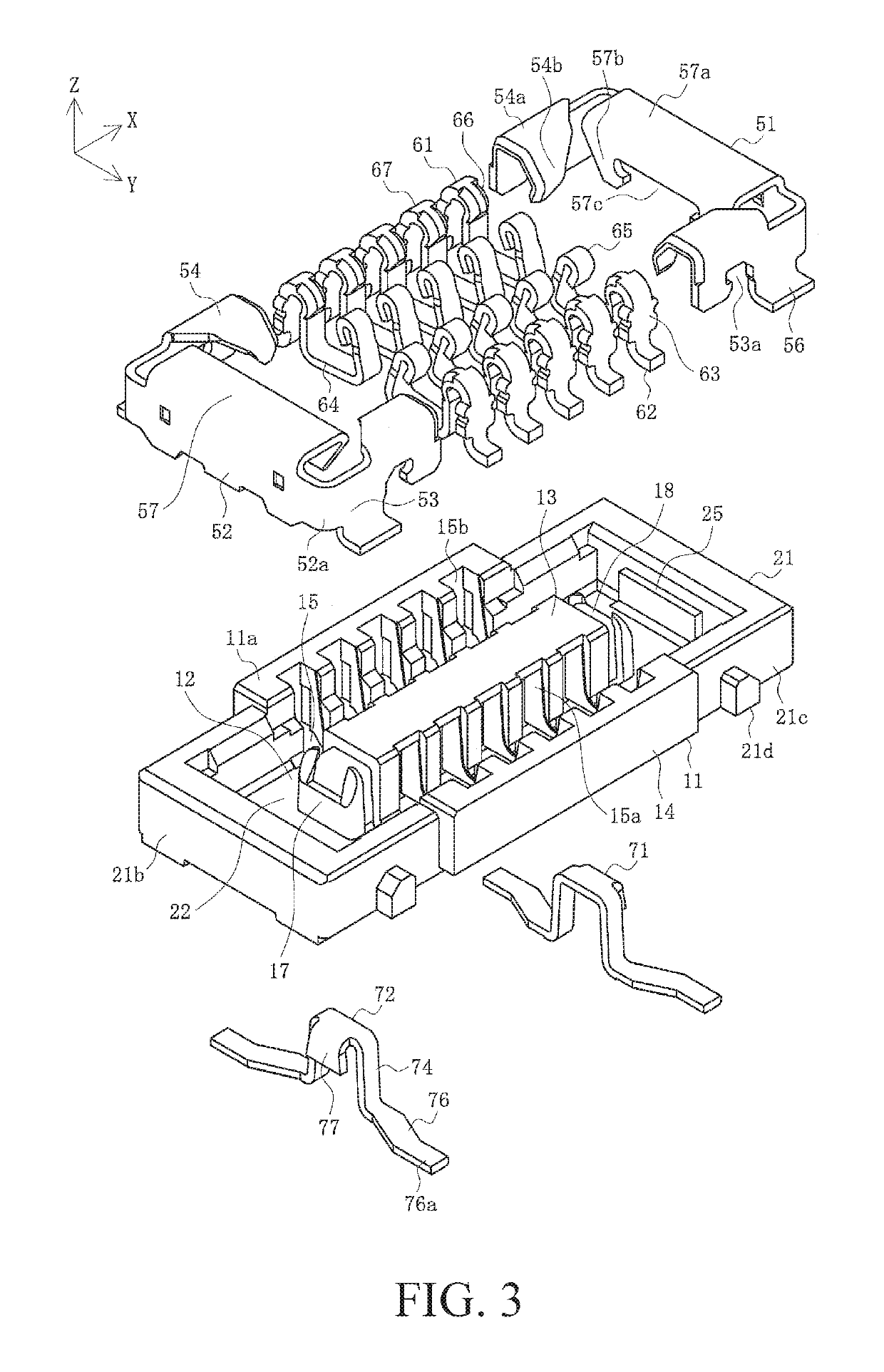
[0026]FIG. 1 is a perspective view of a first connector according to the present embodiment. FIGS. 2A-2D are four surface views of the first connector according to the present embodiment. FIG. 3 is an exploded view of the first connector according to the present embodiment. FIGS. 4A and 4B are cross-sectional views of the first connector according to the present embodiment. FIG. 2A is an upper view, FIG. 2B is a side view, FIG. 2C is a lower view, and FIG. 2D is a front view. FIG. 4A is a cross-sectional view along the A-A line in FIG. 2A, and FIG. 4B is a cross-sectional view along the B-B line in FIG. 2A.

[0027]In the figures, 1 is a connector according to the present embodiment and is the first connector serving as one of a pair of board to board connectors. The first connector 1 is a surface mount type connector mounted on the surface of a first substrate not illustrated in the figure that serves a...


PUM


Abstract

High reliability is achieved with a protected state guaranteed for housings with reinforcing brackets being rigid to be free from displacement and misorientation. A connector includes: a connector body; a terminal installed in the connector body; and a reinforcing bracket fit to the connector body. The connector body includes a recess in which a mating connector body of a mating connector fits, and an insular part that is in the recess and fits in a groove part of the mating connector body. The reinforcing bracket includes an inner reinforcing bracket fit to an insular end part that is an end portion of the insular part in a longitudinal direction. The inner reinforcing bracket includes a body part that is disposed on an upper surface of the insular end part, an end plate that is connected to the body part and is disposed on an end surface of the insular end part, a pair of side plates that are connected to right and left ends of the body part and are disposed on right and left side surfaces of the insular end part, and a pair of connecting legs that are each connected to a lower end of a corresponding one of the side plates and extend outward in a right and left direction of the connector body.

Description

RELATED APPLICATIONS[0001]This application claims priority to Japanese Application No. 2017-093756, filed May 10, 2017, which is incorporated herein by reference in its entirety.TECHNICAL FIELD[0002]The present disclosure relates to a connector.BACKGROUND ART[0003]Conventionally, connectors such as board to board connectors, etc., have been used to electrically connect pairs of parallel circuit boards together. Such connectors are attached to mutually facing surface of a pair of circuit boards and are mated together so that electrical conduction is established. In this context, a technique of maintaining a state of being mated with a mating connector, with reinforcing brackets attached to both end portions serving as lock members, has been proposed (see, for example, Patent Document 1).[0004]FIG. 7 is a perspective view illustrating a conventional connector.[0005]In the figure, 811 is a first housing that is a housing for a first connector mounted on a first circuit board not illust...

Claims


Application Information

Patent Timeline
Patent Type & Authority Patents(United States)
IPC IPC(8): H01R12/00H01R13/504H01R12/71H01R13/631
CPCH01R12/716H01R13/631H01R13/504H01R12/70H01R13/02H01R13/502H01R12/7011H01R12/73H01R13/20H01R13/64
Inventor ONO, HIROKI
Owner MOLEX INC
Why Eureka
Try Eureka