
Elastic wave device

a technology of elastic wave and insertion loss, which is applied in the direction of impedence networks, electrical devices, etc., can solve the problems of increasing the insertion loss of elastic wave devices and reducing the piezoelectricity, and achieve the effect of increasing the insertion loss

Active Publication Date: 2019-04-02
MURATA MFG CO LTD
View PDF21 Cites 0 Cited by
  • Summary
  • Abstract
  • Description
  • Claims
  • Application Information

AI Technical Summary

Benefits of technology

[0006]Accordingly, preferred embodiments of the present invention provide an elastic wave device in which polarization reversal is less likely to occur in a piezoelectric substrate so as to significantly reduce or prevent an increase in the insertion loss.
[0008]According to a specific aspect of various preferred embodiments of the present invention, the second electrode land may be connected to the first busbar of the first interdigital transducer electrode without having the second interdigital transducer electrode interposed therebetween. With this configuration, electric charge generated near the first side portion of the piezoelectric substrate is more easily transferred to the outside. Accordingly, polarization reversal is even less likely to occur in the piezoelectric substrate, thus making it possible to further significantly reduce or prevent an increase in the insertion loss.
[0012]According to another specific aspect of various preferred embodiments of the present invention, the first busbar of the first interdigital transducer electrode may be interposed between the plurality of first and second electrode fingers of the first interdigital transducer electrode and the first side portion of the piezoelectric substrate. With this configuration, electric charge generated near the first side portion is less likely to reach the portion where the first and second electrode fingers of the first interdigital transducer electrode are disposed. Hence, it is less likely that the piezoelectricity at the portion where elastic waves of the first interdigital transducer electrode are excited will be decreased, thus making it possible to effectively significantly reduce or prevent an increase in the insertion loss.
[0013]According to another specific aspect of various preferred embodiments of the present invention, the elastic wave device may further include a plurality of connecting lines that connect the first and second interdigital transducer electrodes and the plurality of electrode lands with each other. Among the plurality of connecting lines, the connecting line that connects the first busbar of the first interdigital transducer electrode and the first electrode land with each other may be located at a position closest to the first side portion of the piezoelectric substrate. With this configuration, electric charge generated near the first side portion of the piezoelectric substrate is more easily transferred to the outside.
[0015]According to preferred embodiments of the present invention, it is possible to provide an elastic wave device in which polarization reversal is less likely to occur in a piezoelectric substrate so as to significantly reduce or prevent an increase in the insertion loss.

Problems solved by technology

Due to the occurrence of polarization reversal, the piezoelectricity may be decreased, which may also increase the insertion loss of the elastic wave device.

Method used


Image

  • Elastic wave device
  • Elastic wave device
  • Elastic wave device

Examples


Embodiment Construction

[0023]Preferred embodiments of the present invention will be described below with reference to the accompanying drawings.

[0024]The preferred embodiments described below are only examples. Note that, among the different preferred embodiments, portions, features or elements of one preferred embodiment may be replaced by or combined with that of another preferred embodiment.

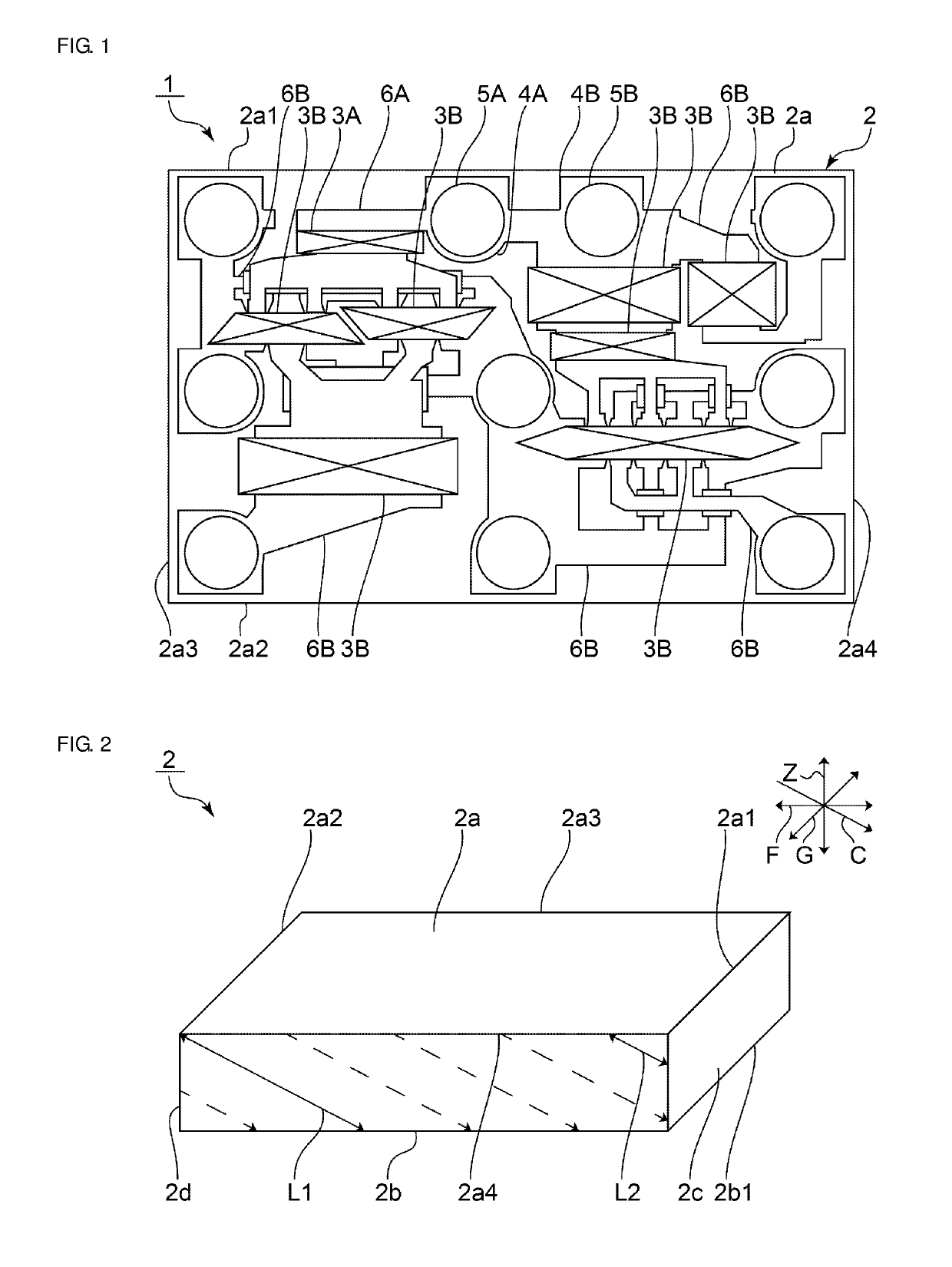
[0025]FIG. 1 is a schematic plan view of an elastic wave device 1 according to a first preferred embodiment of the present invention.

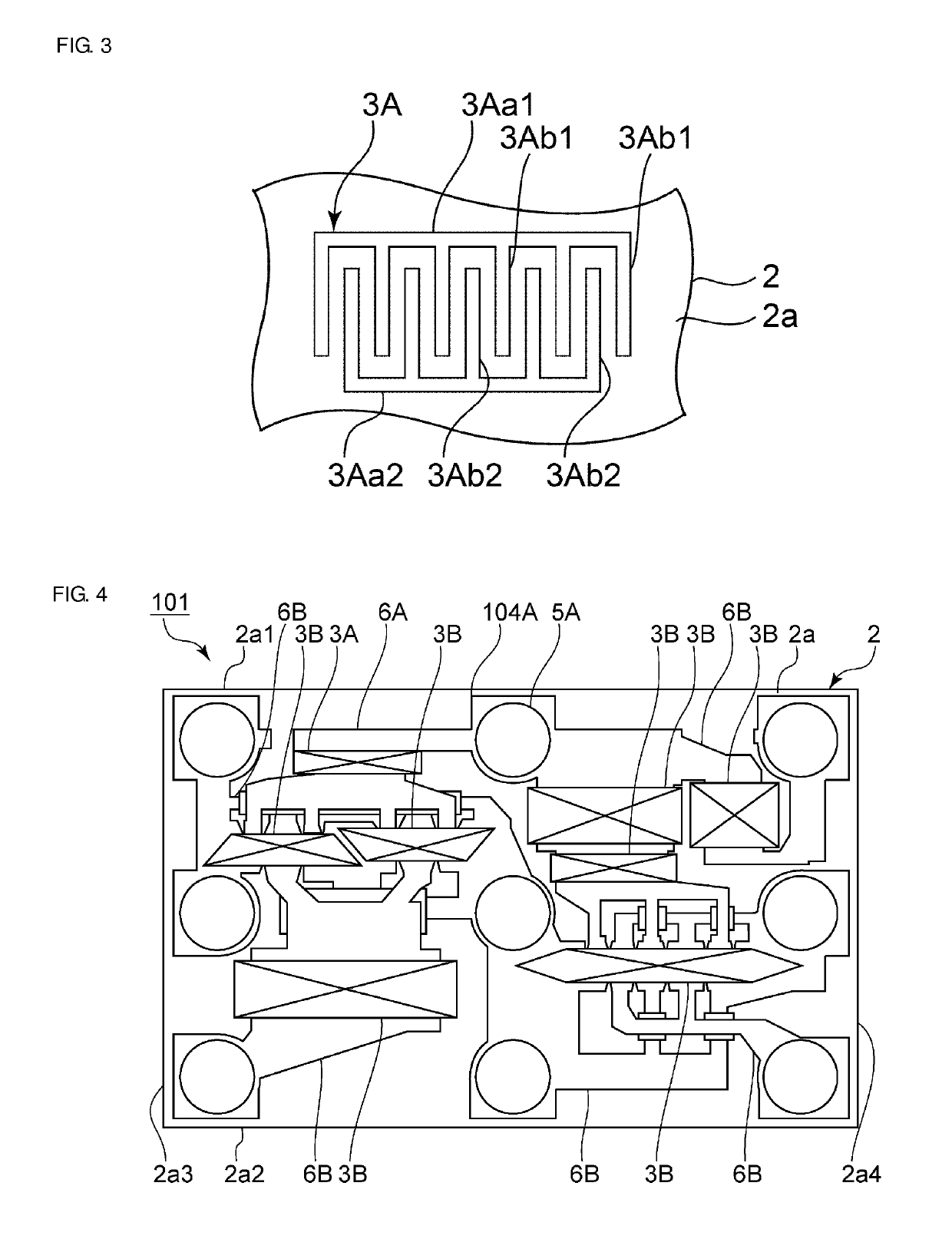
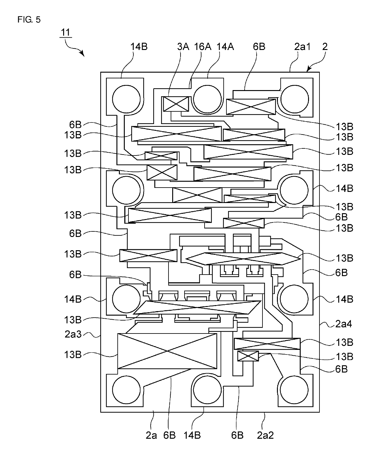
[0026]The elastic wave device 1 includes a piezoelectric substrate 2. The piezoelectric substrate 2 includes a first main surface 2a and a second main surface 2b (shown in FIG. 2) opposing each other. The first and second main surfaces 2a and 2b preferably are rectangular or substantially rectangular. The first main surface 2a include first through fourth side portions 2a1 through 2a4. The piezoelectric substrate 2 is made of a piezoelectric single crystal, such as LiNbO3 and LiTaO3. A...


PUM


Abstract

An elastic wave device includes a piezoelectric substrate, first and second IDT electrodes on a first main surface, and electrode lands each connected to one of the first and second IDT electrodes. First and second side portions extend in a direction perpendicular or substantially perpendicular to a polarization axis direction and to a direction normal to the piezoelectric substrate. The length of the piezoelectric substrate along the polarization axis direction at the first side portion is shorter than that at the second side portion. The first IDT electrode is closer to the first side portion than the second IDT electrode. The electrode lands include a first electrode land connected to the first busbar of the first IDT electrode without having the second IDT electrode interposed therebetween, and a second electrode land being at the same potential as the first busbar of the first IDT electrode.

Description

BACKGROUND OF THE INVENTION[0001]1. Field of the Invention[0002]The present invention relates to an elastic wave device.[0003]2. Description of the Related Art[0004]Elastic wave devices are widely used, for example, in cellular phones. For example, Japanese Unexamined Patent Application Publication No. 2015-002511 discloses an elastic wave device having interdigital transducer (IDT) electrodes. Plural pads are disposed along side portions of one main surface of a piezoelectric substrate of the elastic wave device.[0005]In the piezoelectric substrate of the elastic wave device disclosed in Japanese Unexamined Patent Application Publication No. 2015-002511, polarization reversal easily occurs by the generation of electric charge due to the piezoelectric effect or the pyroelectric effect. Due to the occurrence of polarization reversal, the piezoelectricity may be decreased, which may also increase the insertion loss of the elastic wave device.SUMMARY OF THE INVENTION[0006]Accordingly, ...

Claims


Application Information

Patent Timeline
Patent Type & Authority Patents(United States)
IPC IPC(8): H03H9/02
CPCH03H9/02543H03H9/02992
Inventor YASUDA, JUNPEI
Owner MURATA MFG CO LTD
Learn More